Panel Due 5i White Screen on Duet Mini 5+
-
@phaedrux
wire set up is the 4 wire plug to PanelDue to the IO_0 on the mini 5. I've checked mine against the pinouts and pictures on the paneldue manual pages but will go check it again.
Firmware flashed via USB - PanelDue-3.4.0.
(https://github.com/Duet3D/PanelDueFirmware/releases/download/3.4.0/PanelDueFirmware-logo-3.4.0-5.0i.bin)
I'm using a Mac m1 (we have no windows machines) so had to use the command line tools but the system reported success and on reboot, the logo came up as expected and then the dashboard loaded. I then took the panel due back to the printer and reconnected and white screen reappeared.based on earlier post about this issue was very careful to press the reset and not erase.
-
-
@random_task_1 went into the shop today to refresh the PanelDue via the USB method and when I plugged it into the USB port, it booted up normal and shows normal working modes. Firmware version loaded shows. 3.4.0.
When I plug it back into the Mini 5 Plus, white screen.
I figured I must have something wrong on the wiring but can't figure out what it was. checked wires for the 5 or 6 time and what do you know, I had the wires on the mini 5 backwards. as you can see in the picture I uploaded.
Rewired it properly and it came up as expected -
Based on your photo I don't think you have the wiring correct for the Mini5+.
See the connection guide here: https://docs.duet3d.com/en/User_manual/Connecting_hardware/Display_PanelDue#option-1-4-way-cable
and the mini5 wiring diagram here: https://docs.duet3d.com/duet_boards/duet_3_mini_5_plus/duet_3_mini_5+_wiring_v0.5_v1.0_v1.01.png
Have you tested with the ribbon cable on the mini5 to see if that works?
-
@phaedrux Hi, thanks. The ribbon cable works as expected and I get all functions. The 4 wire going to my IO_0 was wired incorrectly so I fixed that but could not get it past the always "connecting" stage. I'm going to scrap the wire set I have and make up a new one in the next week or so. In the interim, the ribbon cable has me up and running.
-
@random_task_1 To try and get the panel mounted where I want it on the printer, I ordered a set of cables from filastruder to connect between the PanelDue and the Mini 5. I was worried my crimping skills were not up to the task.
The power comes up on the Panel Due and it just has "Connecting" in the top right of the display. I will post pictures of the connection later today. -
Can you check continuity of the wire by testing from where the pins stick out on the back side of both boards? This will show us if the pins, crimps, and wires are all making contact.
Are you able to provide a clearer photo of the PanelDue board?
As an additional sanity check can you post your full config.g and the results of sending M122 and M98 P"config.g" in the gcode console in DWC and copy paste the results here. Also double check the firmware version in PanelDue. settings page.
-
@phaedrux
Continuity checks all good on wires and the board. Wires are new. I'm probably missing something like the proper order of the wires for the pins, but I've looked at the diagrams so much I've gotten myself confused.

Config.g
; Configuration file for Duet 3 Mini 5+ (firmware version 3.3)
; executed by the firmware on start-up
;
; generated by RepRapFirmware Configuration Tool v3.3.10 on Mon Jul 04 2022 15:03:40 GMT-0400 (EDT); General preferences
M575 P1 S1 B57600 ; enable support for PanelDue
G90 ; send absolute coordinates...
M83 ; ...but relative extruder moves
M550 P"LFX301Revo" ; set printer name
M669 K1 ; select CoreXY mode; Wait a moment for the CAN expansion boards to start
G4 S2; Network
M552 S1 ; enable network
M586 P0 S1 ; enable HTTP
M586 P1 S0 ; disable FTP
M586 P2 S0 ; disable Telnet; Drives
M569 P0.0 S1 ; physical drive 0.0 goes forwards / X Axis
M569 P0.1 S1 ; physical drive 0.1 goes forwards / Y Axis
M569 P0.2 S0 ; physical drive 0.2 goes backward / Z Front Left
M569 P0.3 S0 ; physical drive 0.3 goes backward / Z Front Right
M569 P0.4 S0 ; physical drive 0.4 goes backward / Z Rear
M569 P121.0 S1 ; physical drive 121.0 goes forwards / Extrude on Toolboard
M584 X0.0 Y0.1 Z0.2:0.3:0.4 E121.0 ; set drive mapping
M350 X16 Y16 Z16 E16 I1 ; configure microstepping with interpolation
M92 X80.00 Y80.00 Z1600.00:1600.00:1600.00 E415 ; set steps per mm
M566 X900.00 Y900.00 Z180.00:180.00:180.00 E180.00 ; set maximum instantaneous speed changes (mm/min)
M203 X6000.00 Y6000.00 Z180.00:180.00:180.00 E1200 ; set maximum speeds (mm/min)
M201 X1200.00 Y1200.00 Z140.00:140.00:140.00 E140 ; set accelerations (mm/s^2)
M906 X1200 Y1200 Z800:800:800 E800 I30 ; set motor currents (mA) and motor idle factor in per cent
M84 S30 ; Set idle timeout; Axis Limits
M208 X0 Y0 Z0 S1 ; set axis minima
M208 X300 Y300 Z290 S0 ; set axis maxima; Endstops
M574 X1 S3 ; configure sensorless endstop for low end on X
M574 Y1 S3 ; configure sensorless endstop for low end on Y
M574 Z1 S2 ; configure Z-probe endstop for low end on Z; Z-Probe
M950 S0 C"121.io0.out" ; create servo pin 0 for BLTouch
M558 P9 C"121.io0.in" H5 F120 T6000 ; set Z probe type to bltouch and the dive height + speeds
M558 H30 ;*** Remove this line after delta calibration has been done and new delta parameters have been saved
G31 P500 X-19 Y13 Z2.5 ; set Z probe trigger value, offset and trigger height
M557 X20:280 Y20:280 S20 ; define mesh grid; Heaters
M308 S0 P"temp0" Y"thermistor" T100000 B4092 ; configure sensor 0 as thermistor on pin temp0
M950 H0 C"out0" T0 ; create bed heater output on out0 and map it to sensor 0
M307 H0 B0 S1.00 ; disable bang-bang mode for the bed heater and set PWM limit
M140 H0 ; map heated bed to heater 0
M143 H0 S110 ; set temperature limit for heater 0 to 110C
M308 S1 P"121.temp0" Y"thermistor" T100000 B4725 C7.06e-8 ; configure sensor 1 as thermistor on pin 121.temp0
M950 H1 C"121.out0" T1 ; create nozzle heater output on 121.out0 and map it to sensor 1
M307 H1 B0 S1.00 ; disable bang-bang mode for heater and set PWM limit
M143 H1 S300 ; set temperature limit for heater 1 to 300C; Fans
M950 F0 C"out5" Q500 ; create fan 0 on pin out5 and set its frequency
M106 P0 C"CASEFAN" S1 H-1 ; set fan 0 name and value. Thermostatic control is turned off
M950 F1 C"121.out2" Q500 ; create fan 1 on pin 121.out1 and set its frequency
M106 P1 C"HOTEND" S1 H1 T40 ; set fan 1 name and value. Thermostatic control is turned on
M950 F2 C"121.out1" Q500 ; create fan 2 on pin 121.out2 and set its frequency
M106 P2 C"PARTFAN" S0 H-1 ; set fan 2 name and value. Thermostatic control is turned off; Tools
M563 P0 S"E3DRevo" D0 H1 F2 ; define tool 0
G10 P0 X0 Y0 Z0 ; set tool 0 axis offsets
G10 P0 R0 S0 ; set initial tool 0 active and standby temperatures to 0C; Custom settings are not defined
; Miscellaneous
M501 ; load saved parameters from non-volatile memory
M911 S10 R11 P"M913 X0 Y0 G91 M83 G1 Z3 E-5 F1000" ; set voltage thresholds and actions to run on power loss
T0 ; select first toolM122:
7/20/2022, 3:38:50 PM M98 P"config.g"
HTTP is enabled on port 80
FTP is disabled
TELNET is disabled
Warning: Heater 1 predicted maximum temperature at full power is 488°C
7/20/2022, 3:38:32 PM M122
=== Diagnostics ===
RepRapFirmware for Duet 3 Mini 5+ version 3.4.1 (2022-06-01 21:06:56) running on Duet 3 Mini5plus WiFi (standalone mode)
Board ID: QN6U2-H096U-D65J0-40KMJ-LQ03Z-RJJPD
Used output buffers: 3 of 40 (21 max)
=== RTOS ===
Static ram: 103684
Dynamic ram: 110396 of which 12 recycled
Never used RAM 27620, free system stack 196 words
Tasks: NETWORK(ready,14.9%,224) HEAT(notifyWait,0.0%,373) Move(notifyWait,0.0%,363) CanReceiv(notifyWait,0.0%,772) CanSender(notifyWait,0.0%,372) CanClock(delaying,0.0%,346) TMC(notifyWait,0.7%,114) MAIN(running,83.3%,412) IDLE(ready,0.3%,29) AIN(delaying,0.8%,264), total 100.0%
Owned mutexes: WiFi(NETWORK)
=== Platform ===
Last reset 00:02:21 ago, cause: power up
Last software reset at 2022-07-04 17:01, reason: User, GCodes spinning, available RAM 27472, slot 0
Software reset code 0x0003 HFSR 0x00000000 CFSR 0x00000000 ICSR 0x00000000 BFAR 0xe000ed38 SP 0x00000000 Task MAIN Freestk 0 n/a
Error status: 0x00
Aux0 errors 0,0,0
MCU revision 3, ADC conversions started 141130, completed 141129, timed out 0, errs 0
Step timer max interval 1488
MCU temperature: min 28.0, current 32.6, max 32.8
Supply voltage: min 23.7, current 23.7, max 23.8, under voltage events: 0, over voltage events: 0, power good: yes
Heap OK, handles allocated/used 0/0, heap memory allocated/used/recyclable 0/0/0, gc cycles 0
Events: 0 queued, 0 completed
Driver 0: standstill, SG min 0, read errors 0, write errors 0, ifcnt 11, reads 7396, writes 11, timeouts 0, DMA errors 0, CC errors 0
Driver 1: standstill, SG min 0, read errors 0, write errors 0, ifcnt 11, reads 7396, writes 11, timeouts 0, DMA errors 0, CC errors 0
Driver 2: standstill, SG min 0, read errors 0, write errors 0, ifcnt 11, reads 7396, writes 11, timeouts 0, DMA errors 0, CC errors 0
Driver 3: standstill, SG min 0, read errors 0, write errors 0, ifcnt 11, reads 7395, writes 11, timeouts 0, DMA errors 0, CC errors 0
Driver 4: standstill, SG min 0, read errors 0, write errors 0, ifcnt 11, reads 7396, writes 11, timeouts 0, DMA errors 0, CC errors 0
Driver 5: not present
Driver 6: not present
Date/time: 2022-07-20 15:38:31
Cache data hit count 275859819
Slowest loop: 13.91ms; fastest: 0.13ms
=== Storage ===
Free file entries: 10
SD card 0 detected, interface speed: 22.5MBytes/sec
SD card longest read time 3.4ms, write time 0.0ms, max retries 0
=== Move ===
DMs created 83, segments created 0, maxWait 0ms, bed compensation in use: none, comp offset 0.000
=== MainDDARing ===
Scheduled moves 0, completed 0, hiccups 0, stepErrors 0, LaErrors 0, Underruns [0, 0, 0], CDDA state -1
=== AuxDDARing ===
Scheduled moves 0, completed 0, hiccups 0, stepErrors 0, LaErrors 0, Underruns [0, 0, 0], CDDA state -1
=== Heat ===
Bed heaters 0 -1 -1 -1, chamber heaters -1 -1 -1 -1, ordering errs 0
Heater 1 is on, I-accum = 0.0
=== GCodes ===
Segments left: 0
Movement lock held by null
HTTP is idle in state(s) 0
Telnet is idle in state(s) 0
File is idle in state(s) 0
USB is idle in state(s) 0
Aux is idle in state(s) 0
Trigger is idle in state(s) 0
Queue is idle in state(s) 0
LCD is idle in state(s) 0
SBC is idle in state(s) 0
Daemon is idle in state(s) 0
Aux2 is idle in state(s) 0
Autopause is idle in state(s) 0
Code queue is empty
=== CAN ===
Messages queued 1279, received 2810, lost 0, boc 0
Longest wait 3ms for reply type 6053, peak Tx sync delay 3, free buffers 18 (min 17), ts 706/705/0
Tx timeouts 0,0,0,0,0,0
=== Network ===
Slowest loop: 20.34ms; fastest: 0.00ms
Responder states: HTTP(0) HTTP(0) HTTP(0) HTTP(0) FTP(0) Telnet(0), 0 sessions
HTTP sessions: 1 of 8- WiFi -
Network state is active
WiFi module is connected to access point
Failed messages: pending 0, notready 0, noresp 0
WiFi firmware version 1.26
WiFi MAC address f0:08:d1:03:80:43
WiFi Vcc 3.49, reset reason Power up
WiFi flash size 2097152, free heap 24240
WiFi IP address 192.168.1.46
WiFi signal strength -50dBm, mode 802.11n, reconnections 0, sleep mode modem
Clock register 00002002
Socket states: 0 0 0 0 0 0 0 0
- WiFi -
-
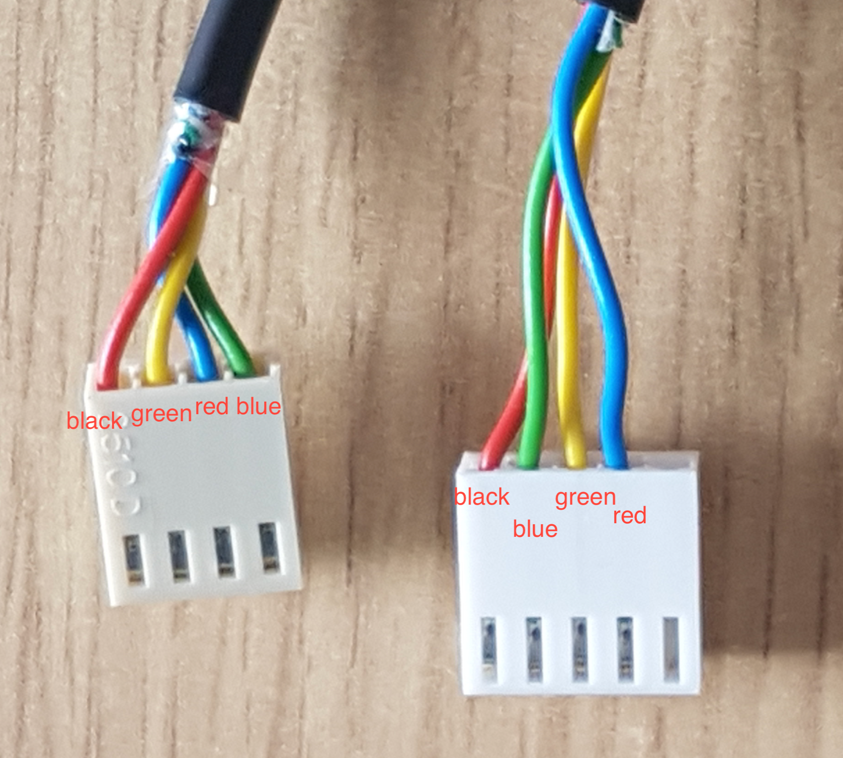
@random_task_1 Your pinout is incorrect.
I've taken the photo in the documentation, and overlaid your wire colors in text. The 4 pin side represents what your 4 pin side is. The 5 pin side represents what your 5 pin side should be. Looks to me like you've got the RX/TX flipped, which is why your screen is powering up (5v and GND are good) but not communicating.
-
@elmoret Thanks
Swapped the cables. still same error. Constant "Connecting"


-
@random_task_1 Not sure how to mark this solved but it was the cable order. I finally got them properly seated in the housing in the right order and, what do you know they worked......thanks for the help
-
 undefined droftarts marked this topic as a question
-
undefined droftarts has marked this topic as solved


