Trying to fix my height map offset issue
-
Hey all, been a while and I hope everyone is doing well!
I wanted to see if I could get some help to correct my
Height Mapvisual in my DWC panel
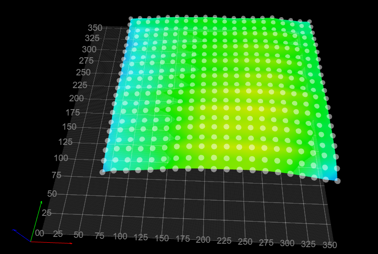
I think this is because of my axis offsets due to my fan and hemera setup, but not entirely sure. I do know that my corners print better than my centre and even after fixing z-offset, z-probe trigger, and baby stepping, my centre is still still printing too high compared to my outer regions and thought it's time I try to fix this.
Board: Duet 2 WiFi (2WiFi)
Firmware: RepRapFirmware for Duet 2 WiFi/Ethernet 3.4.1 (2022-06-01)
Duet WiFi Server Version: 1.26Here's a few excerpts from my config.g file:
BL-Touch Probe Offsets
global probe_offset_x		 = 30		  ; BL Touch X offset
global probe_offset_y		 = 36		  ; BL Touch Y offset
global probe_offset_z		 = 3.585	  ; BL Touch Z offset
Axis Min/Max
M208 S1 X5 Y0 Z-10                                 ; set axis minima
M208 S0 X355 Y355 Z400                             ; set axis maxima
This is from my mesg.g file, where I reckon the problem lies, but when I previously tried to fix these, I wouldn't be able to run a 20pt G29 as it couldn't reach areas.
M557 X60:380 Y90:390 P20And just in case, here's my full config.g file
; Configuration file for Duet WiFi (firmware version 3)
; executed by the firmware on start-up

; ######################################################
; General preferences
; ######################################################
G90                                                ; send absolute coordinates...
M83                                                ; ...but relative extruder moves
M550 P"Stargate SG-1 - Jackson"                    ; set printer name

; ######################################################
; Global Variables
; ######################################################

global g_move_forward        = 5          ; can be used to always move Z to known height
global g_move_back           = -{global.g_move_forward}          ; can be used to always move Z to known height
global g_axes_speeds		 = 8000 ; Speeds to move axes during homing

; Z-Lead Screw Positions
global l_zlead_screw_x		 = 57
global r_zlead_screw_x		 = 353
global zlead_screw_y		 = 217

; 4-P Bed Levelling Positions
global fl_screw_x		 = 57
global fl_screw_y		 = 88
global fr_screw_x		 = 353
global fr_screw_y		 = 88
global bl_screw_x		 = 57
global bl_screw_y		 = 345
global br_screw_x		 = 353
global br_screw_y		 = 345

global g_print_end_mode      = "HEAT OFF" ; determines if heaters are turned off when print is done
global g_map_mode            = "FULL"     ; determines which kind of height map is created/loaded
global g_probe_mode          = "TWO"      ; determines if z proving used consecutive or averaging
global g_level_mode          = "3PT"      ; determines if 3 or 4 points are used for leveling

; BL-Touch Probe Offsets
global probe_offset_x		 = 30		  ; BL Touch X offset
global probe_offset_y		 = 36		  ; BL Touch Y offset
global probe_offset_z		 = 3.585	  ; BL Touch Z offset

; ######################################################
; Network
; ######################################################
M552 S1                                            ; enable network
M586 P0 S1                                         ; enable HTTP
M586 P1 S0                                         ; disable FTP
M586 P2 S0                                         ; disable Telnet

; ######################################################
; Drives
; ######################################################
M569 P0 S0                                         ; X drive 0 goes backwards
M569 P1 S1                                         ; Y drive 1 goes backwards
M569 P2 S1                                         ; Z1 drive 2 goes forwards
M569 P3 S0                                         ; E drive 3 goes backwards
M584 X0 Y1 Z2 E3                                   ; set drive mapping

; ######################################################
; Movement
; ######################################################
M350 X16 Y16 Z16 E16 I1                            ; configure microstepping with interpolation
M92 X80.00 Y80.00 Z800.00 E409                     ; set steps per mm
M566 X900.00 Y900.00 Z300.00 E2000.00 P1           ; set maximum instantaneous speed changes (mm/min)
M203 X6000.00 Y6000.00 Z900.00 E6000.00            ; set maximum speeds (mm/min)
M201 X500.00 Y500.00 Z500.00 E3000.00              ; set accelerations (mm/s^2) 200
M906 X800 Y800 Z800 E800 I30                       ; set motor currents (mA) and motor idle factor in per cent
M84 S30                                            ; Set idle timeout

; ######################################################
; Axis Min/Max
; ######################################################
M208 S1 X5 Y0 Z-10                                 ; set axis minima
M208 S0 X355 Y355 Z400                             ; set axis maxima

; ######################################################
; Endstops
; ######################################################
M574 X2 S1 P"xstop"                                ; configure active-high endstop for low end on X via pin xstop
M574 Y2 S1 P"ystop"                                ; configure active-high endstop for low end on Y via pin ystop
M574 Z1 S2                                         ; configure Z-probe endstop for low end on Z

; ######################################################
; Kinematics
; ######################################################
M669 K0

; ######################################################
; Custom Probe config file
; ######################################################
M98 P"configs/probe_config.g"                         ; Config settings for my EZABL probe

; ######################################################
; Heaters
; ######################################################
M308 S0 P"bedtemp" Y"thermistor" T100000 B4138     ; configure sensor 0 as thermistor on pin bedtemp
M950 H0 C"bedheat" T0                              ; create bed heater output on bedheat and map it to sensor 0
M307 H0 B0 S1.00                                   ; disable bang-bang mode for the bed heater and set PWM limit
M140 H0                                            ; map heated bed to heater 0
M143 H0 S120                                       ; set temperature limit for heater 0 to 120C
M308 S1 P"e0temp" Y"thermistor" T100000 B4138      ; configure sensor 1 as thermistor on pin e0temp
M950 H1 C"e0heat" T1                               ; create nozzle heater output on e0heat and map it to sensor 1
M307 H1 B0 S1.00                                   ; disable bang-bang mode for heater  and set PWM limit
M143 H1 S285                                       ; set temperature limit for heater 1 to 280C

; ######################################################
; Fans
; ######################################################
M950 F0 C"nil"									   ; Free up pin F0
M950 F0 C"fan1" Q500							   ; Assign Fan0 for Prusa Slicer and default for other slicers
M106 P0 S0 H-1
M950 F1 C"nil"									   ; Free up pin F0
M950 F1 C"fan0" Q500                               ; create fan 0 on pin fan3 and set its frequency
M106 P1 S1 H1 T80                                  ; set fan 1 value. Thermostatic control is turned on

; ######################################################
; Tools
; ######################################################
M563 P0 D0 H1 F0                                   ; define tool 0
G10 P0 X0 Y0 Z0                                    ; set tool 0 axis offsets
G10 P0 R0 S0                                       ; set initial tool 0 active and standby temperatures to 0C

; ######################################################
; Probe points for my 2x Z Lead Screws
; ######################################################
;M671 X{global.fl_screw_x}:{global.fr_screw_x}:{global.bl_screw_x}:{global.br_screw_x} Y{global.fl_screw_y}:{global.fr_screw_y}:{global.bl_screw_y}:{global.br_screw_y}
M671 X30:310:30:310 Y76.8:76.8:338:338

; ######################################################
; Custom Configurations
; ######################################################

; Filament Runout Sensor
M591 D0 P1 C"e0stop" S1

; TFT Display Config
M575 P1 S1 B57600

; Miscellaneous
M911 S10 R11 P"M913 X0 Y0 G91 M83 G1 Z3 E-5 F1000" ; set voltage thresholds and actions to run on power loss
M501                                               ; load saved parameters from non-volatile memory
Any guidance or ideas would be much appreciated!
Cheers
TimEnder 5 Plus - E3D Hemera Hotend - Duet 2 Wifi
-
@infidelprops LOL - printer with Stargate references!
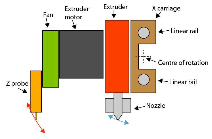
With that shape, I'd guess that the X axis is twisting a bit under the weight of the extruder carriage as it moves across the length, and with the probe offsets the affect is magnified. Something like (but maybe not as extreme):
To test, you can do a manual bed mesh, where you do a bed mesh but manually jog the nozzle until it touches the bed/feeler gauge/piece of paper. Set M558 probe type to P0 and run a bed mesh, and you will be prompted to jog the nozzle down to the bed surface whenever the probe is called. This eliminates any probe tilt and will give you a more accurate view of what the bed surface is like. It is time consuming, but should show where the issue lies.
Ian
Bed-slinger - Mini5+ WiFi/1LC | RRP Fisher v1 - D2 WiFi | Polargraph - D2 WiFi | TronXY X5S - 6HC/Roto | CNC router - 6HC | Tractus3D T1250 - D2 Eth
-
@infidelprops
My BLTouch gives me wrong values because of the magnetic print bed.
Maybe it also applies to you?
In this Thread you can read what I did to make the BLTouch values a little more accurate.Google Translate
--- Original Text ---Mein BLTouch liefert mir wegen des magnetischen Druckbettes falsche Werte.
Vielleicht trifft es auch bei Dir zu ?
In diesem Thread kannst Du lesen was ich dagegen getan habe um die Werte vom BLTouch etwas genauer werden zu lassen.DDA5X... 0.9° Stepper... Linearrails... Duet 2 Wifi... PT100 Board... Duet IR-Probe... Dyze Pro Kit up to 500°C.. etc
Thingiverse -
P.S.:
I installed two sensors.
The dc42-IR-Probe and the BLTouch.
After shielding the BLTouch a bit from the magnetic field of the pressure plate, it got noticeably better, as can be seen in the screenshots I posted in the linked thread.But still today the heightmap from the BLTouch towards the middle is a bit higher than the heightmap from the IR-Probe.
As if it were an inflated pillow.
The values in the middle of the print bed are on average 0.08mm higher than those from the IR probe.
Towards the edges, they are almost identical.Therefore, when I get the chance, I will build my own sample that works for all printing surfaces and that is not affected by magnetic interference fields.
But at the moment I'm looking for an apartment, so everything can take a while.The IR probe is my main sensor, but it has its issues on some surfaces, so I'd like to have an alternate sensor to use.
The nozzle and both sensors are measured exactly using one of the adjusting screws (level screws).
I drew a cross on the print bed with a pencil for exact orientation.
Position the nozzle at a height of 0.05mm above the measuring cross and then level the print bed with a 0.05mm spring steel sheet.
With the IR probe, I determined the scanning area (which you can't see) by sticking a sewing thread on the print bed in the X direction (fixed at the ends with adhesive tape) and then I used the IR probe in Z positioned, which he only triggers on the sewing thread and then I calculated the offset to the nozzle.
The same then in the direction of the Y-axis.
I then had both sensors sample this point 10x and then added the 10 values from the console and divided by 10 to get an exact z-offset for each sensor.
Therefore the measuring points of the BLTouch and the IR-Probe are very precise and always in exactly the same place.Google Translate
--- Original Text ---Ich habe zwei Sensoren verbaut.
Den dc42-IR-Probe und den BLtouch.
Nachdem ich den BLTouch etwas gegen das magnetische Feld der Druckplatte abgeschirmt habe, ist es merklich besser geworden, wie auch in den Screenshots zu sehen die ich in dem verlinkten Thread gepostet habe.Aber heute noch sind die Heightmap vom BLTouch zur Mitte hin etwas höher wie die Heightmap vom IR-Probe.
Als wäre es ein aufgeblasenes Kissen.
Die Werte in der Mitte des Druckbettes liegen im Schnitt 0,08mm höher als die vom IR-Probe.
Zu den Rändern hin sind sie fast identisch.Daher werde ich mir bei Gelegenheit einen eigenen Probe bauen der für alle Druckoberflächen funktioniert und dem magnetische Störfelder nichts ausmachen.
Aber zZ bin ich auf Wohnungssuche und daher kann sich alles etwas hin ziehen.Der IR-Probe ist mein Haupt-Sensor, aber er hat bei manchen Oberflächen seine Probleme, daher hätte ich gerne einen alternativen Sensor den ich dann nutzen kann.
Die Düse und beide Sensoren werden exakt über eine der Stellschrauben (Levelschrauben) eingemessen.
Dazu habe ich mit einem Bleistift ein Kreuz zur exakten Orientierung auf das Druckbett gezeichnet.
Die Düse mit einer Höhe von 0,05mm über dem Messkreuz positioniert und dann mit einem 0,05mm Federstahlblech das Druckbett gelevelt.
Beim IR-Probe habe ich die Abtastfläche (die man ja nicht sieht) so ermittelt, dass ich einen Nähfaden in X Richtung auf das Druckbett geklebt habe (an den Enden mit einem Klebestreifen fixiert) und dann habe ich den IR-Probe so in Z positioniert, das er nur auf dem Nähfaden auslöst und habe dann den Offset zur Düse errechnet.
Das gleiche dann in Richtung der Y-Achse.
Beide Sensoren habe ich dann 10x diesen Punkt abtasten lassen und habe dann die 10 Werte aus der Konsole addiert und durch 10 dividiert um ein genaues Z-Offset jedes Sensors zu erhalten.
Daher sind die Messpunkte vom BLTouch und vom IR-Probe sehr exakt und immer auf exakt der gleichen Stelle.DDA5X... 0.9° Stepper... Linearrails... Duet 2 Wifi... PT100 Board... Duet IR-Probe... Dyze Pro Kit up to 500°C.. etc
Thingiverse -
@droftarts hahaha! Yes, I do love my Stargate!
And thanks for the tips! I've got a E3D Hemera with a small 4010 fan on the side, and probe on the front left, so the fan and carriage being on the left (where the blue lines hang) could definitely be an issue I haven't considered.
The area I'd love to fix, is how off the visual of my Height Map is, from my Print Bed. Is this fixable or because of my mesh.g settings, I just have to live with this?
-
@norder Great, write-up mate, thanks for referencing this and I will look into this magnetic shielding... and gives me an excuse to buy some cookies.
