Duet 3 Mini 5+ Out 5 and 6 Not Working No Power
-
I got a new Duet 3 Mini 5+ with my 3D printer, and setup per RatRig's recommendation using Out3 and 4. Today i wanted to expand my connections so i tried using Out 5 and 6, and they both seem dead. I tried changing the jumper to both 12V and VIN (24V) and i get nothing across those pins. I activated output 5 in my config.g file. Is there something i am missing or do i have a defective board?
-
@rogerpodacter the outside two pins of the OUT_5&6 Select V jumper should be VIN_fused and 12V. Measure between each of those and GND (not the centre pin). If you get no voltage there, check the main fuse, next to the VIN barrier strip.
The OUT connectors are switched on the GND side (because that’s how MOSFETs work), so measuring between voltage in and OUT6 pin (for example) will show no voltage, unless out6 is configured and turned on.
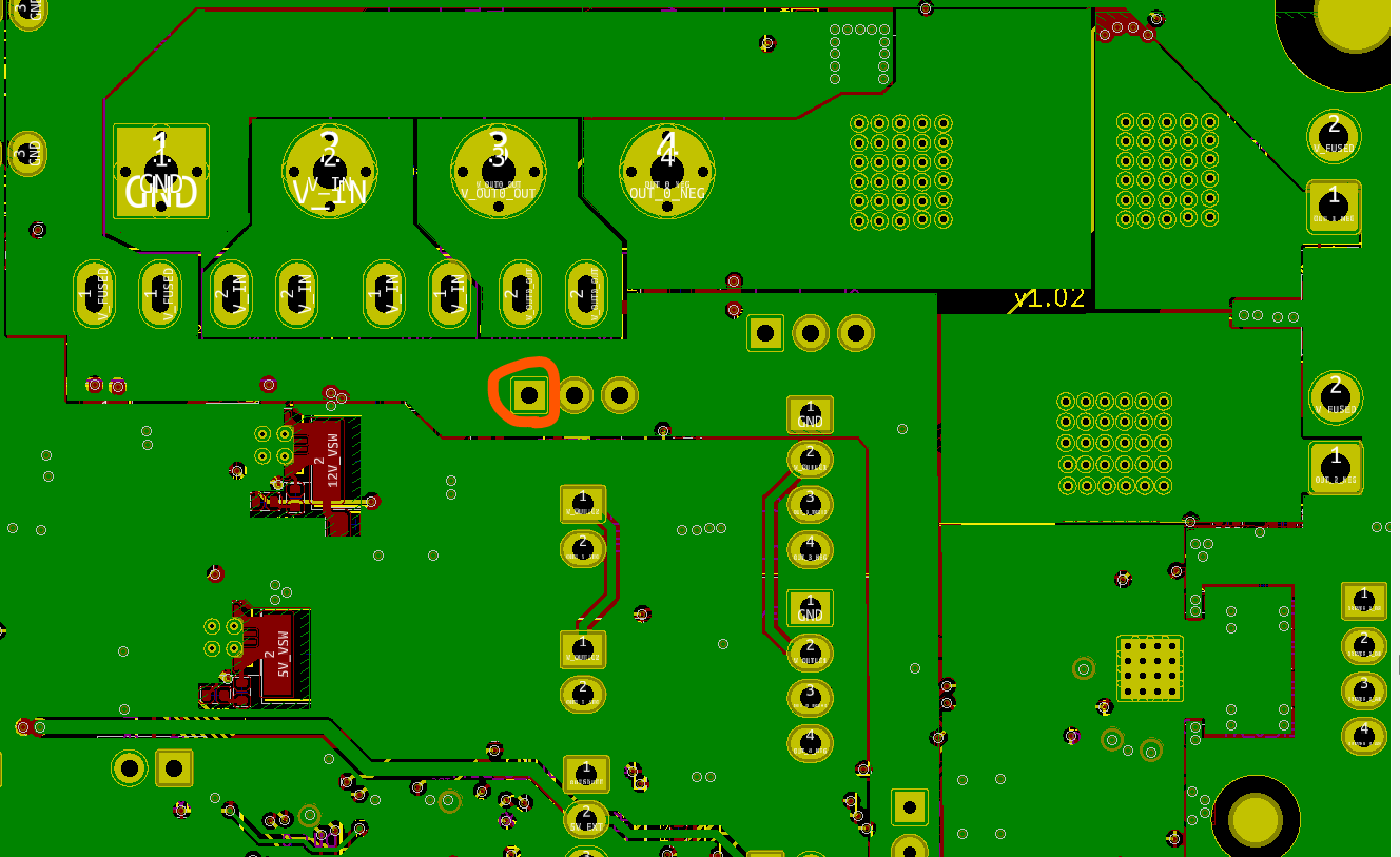
If that doesn’t help, post a good picture of your board, showing the voltage selector jumper pins.
Ian
Bed-slinger - Mini5+ WiFi/1LC | RRP Fisher v1 - D2 WiFi | Polargraph - D2 WiFi | TronXY X5S - 6HC/Roto | CNC router - 6HC | Tractus3D T1250 - D2 Eth
-
@droftarts EDIT: nevermind i got it, thanks for the help. I was being dumb measuring across the wrong pins. All is good now.
ORIGINAL MESSAGE: so i still seem to have an issue. with the jumper in the left position (not the stock default position), i measure the jumpered pins against ground and i read 12V. but when i move the jumper over to the right VIN, jumper to ground gives 0.112V.
I also enabled out5 in config.g and measured directly between V_OUTCL2+ and out5-. i got 12V for the first config but the VIN showed zero volts.
Both fuses are not burst and in good condition. I'm stumped.
-
@rogerpodacter that VIN pin and the corresponding pin on the voltage select jumper for OUT3/OUT4 are connected by a wide trace on the underside of the board. I suggest you check that the soldering of that VIN jumper pin on the underside of the board looks OK. It's unlikely to be bad, but worth a quick visual inspection.