Duet 3 Toolboard and SuperPinda Inductive Z Probe
-
I just begain wiring my new Duet 3 Toolboard, and i started with my Z probe. But i cannot get it to function correctly. On my Duet 3 Mini 5+ the probe worked normally, all i did was change the input to the new input of the toolboard. Below is my config.g file. The probe on the main board was connected to io3.in, and i simply switched that to io0.in for the toolboard.
On the DWC the probe reads 1000 always, but on the PanelDue 5i, the probe fluctuates from 850 to 712. But they are false values because they dont react whether i put a metal beneath it or move the probe away from the bed. They always bounce around randomly meaninglessly.
Am i missing something obvious? Do i have to add a command to account for the toolboard?
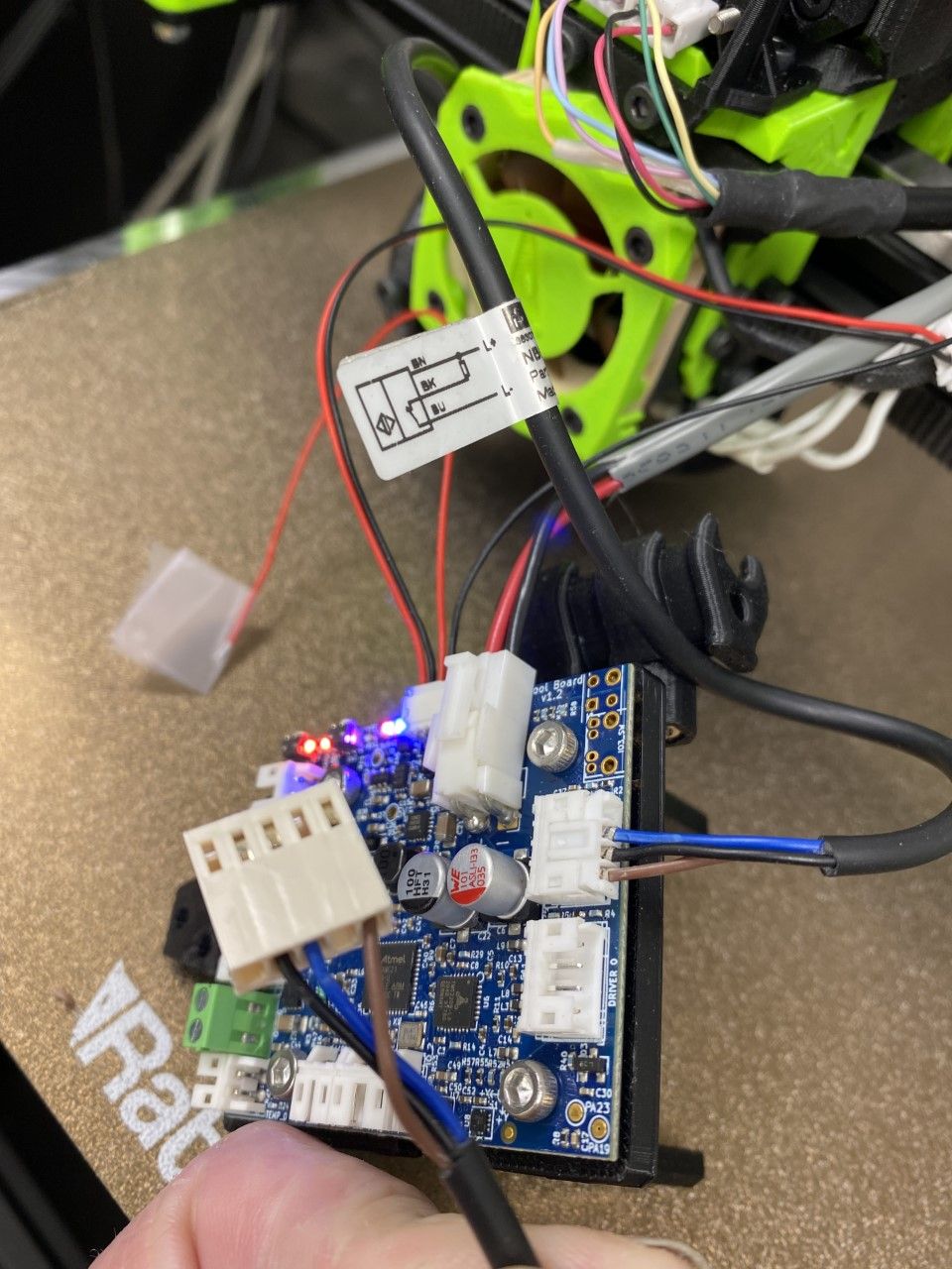
; General preferences
G90                                     ; send absolute coordinates...
M83                                     ; ...but relative extruder moves
M550 P"V-Core3"                         ; set printer name
M669 K1                                 ; CoreXY
G21                                     ; Set Units to Millimeters

; Network
M552 S2                                 ; enable network
M586 P0 S1                              ; enable HTTP
M586 P1 S0                              ; disable FTP
M586 P2 S0                              ; disable Telnet

G4 S2 ; wait for expansion boards to start

; Drives
M569 P0.0 S0 D2	                        ; Left Z physical drive 0.0 goes forwards
M569 P0.1 S0 D2                         ; Rear Z physical drive 0.1 goes forwards
M569 P0.2 S0 D2                            ; Right Z physical drive 0.2 goes forwards
M569 P0.3 S1 D2                            ; Right physical drive 0.3 goes forwards
M569 P0.4 S1 D2                            ; Left physical drive 0.4 goes forwards
M569 P0.5 S1 D2                            ; Extruder physical drive 0.5 goes forwards
M584 X0.4 Y0.3 Z0.0:0.1:0.2 E0.5        ; set drive mapping
M350 X16 Y16 Z16 E16 I1                 ; configure microstepping with interpolation

M92 X80.00 Y80.00 Z800.00 E400               ; set steps per mm
M906 X1400 Y1400 Z1400 E600 I30              ; set motor currents (mA) and motor idle factor in per cent -- safe for Duet 3 mini 5+
M84 S30                                 ; Set idle timeout

M566 X1000.00 Y1000.00 Z6.00 E120.00 P1          ; set maximum instantaneous speed changes (mm/min)
M203 X30000.00 Y30000.00 Z1000.00 E3600.00     ; set maximum speeds (mm/min)
M201 X12000.00 Y12000.00 Z100.00 E3600.00        ; set accelerations (mm/s^2)

; Axis Limits
M208 X0 Y0 Z0 S1                               ; set axis minima
M208 X310 Y310 Z300 S0                         ; set axis maxima

; Endstops
M574 X1 S1 P"io4.in"                           ; configure active high endstops
M574 Y2 S1 P"io1.in"                           ; configure active high endstops

M671 X-4.5:150:304.5 Y-4.52:305:-4.52 S5       ; define positions of Z leadscrews or bed levelling screws
M557 X20:280 Y20:280 P5                        ; define 5x5 mesh grid

; Heaters
M308 S0 P"temp0" Y"thermistor" T100000 B3950 A"Bed"    ; configure sensor 0 as thermistor on pin temp0
M950 H0 C"out0" T0 Q10												; Define Heater0 as the heated bed, bind to Sensor0
M140 H0 P0															; Define Heated Bed
M307 H0 A303.1 C356.7 D1.4 S1.00 V24.0 B0
;M307 H0 R0.860 C439.9 D11.80 S1.00 B0							; PID Tuning for Heater0, Heated Bed (45C)
M143 H0 S110														; Set temperature limit for Heater0 to 120C

M308 S1 P"temp1" Y"thermistor" T100000 B4725 C7.060000e-8 A"Hotend"
M950 H1 C"out1" T1													; Define Heater1 as Extruder0 heater, bind to Sensor1
M307 H1 R3.075 K0.558:0.000 D4.86 E1.35 S1.00 B0 V24.0
;M307 H1 R2.794 C119.4:105.8 D3.09 S1.00 V24.1 B0					; PID Tuning for Heater1, Extruder0 (200C)
;M307 H1 A751.5 C196.6 D4.7 S1.00 V23.9 B0
M143 H1 S285														; Set temperature limit for heater 1 to 285C
;M308 S2 P"temp2" Y"thermistor" A"Chamber" T100000 B4725 C7.060000e-8; Define Sensor2 as Chamber temperature (Semitec 104GT2)
M308 S3 Y"mcu-temp" A"MCU"											; Define Sensor3 as the integrated MCU temperature sensor
M308 S4 Y"drivers" A"TMC Drivers"									; Define Sensor4 as the TMC overheat sensor

; Fans
M308 S2 Y"drivers" A"4028 Power"    								; configure sensor 0 as thermistor on pin temp0
M950 H2 C"!out2" T2 Q10												; Define Heater2 as the 4028 fan power, bind to Sensor2
M143 H2 P2 S200
;M307 H2 I1 S1
;M106 P2 C"4028 Power" S0 H-1										; 4028 power using spare heater

;M950 F0 C"out4" Q500                   							; create fan 0 on pin out4 and set its frequency
M950 F0 C"!out4+out4.tach" Q25000
M106 P0 C"Layer Fan" S0 L0.0 X1.0 H-1
;M106 P0 C"Layer Fan" S0 H-1            							; set fan 0 name and value. Thermostatic control is turned off

;M950 F1 C"out3" Q500                   ; create fan 1 on pin out3 and set its frequency
M950 F1 C"out3+out3.tach" 				; Fan 1 uses out3, and using out3.tach as a tacho input
M106 P1 C"Hotend Fan" S0 H1 T45        ; set fan 1 name and value. Thermostatic control turned on for Hotend

;M950 F1 C"out5" Q500                   ; create fan 1 on pin out5 and set its frequency
;M106 P1 C"Hotend Fan" S0 H1 T45        ; set fan 1 name and value. Thermostatic control turned on for Hotend

; Tools
M563 P1 D0 H1 F0 S"Mosquito Magnum"           										; define tool 0
G10 P1 X0 Y0 Z0            ; set tool 0 axis offsets
G10 P1 R190 S0               ; set initial tool 0 active 60C and standby temperatures to 0C

;M563 P0 H0 F0 S"Keenevo 600W Bed"
;G10 P0 X0 Y0 Z0
;G10 P0 R50 S0

; EVA 2 / BMG / E3D V6

;M92 E400          ; set extruder steps per mm, 0.9 angle/step (LDO Pancake)
;M906 E800         ; set extruder motor current (mA) and idle factor in per cent

;M308 S1 P"temp1" Y"thermistor" T100000 B4725 C7.060000e-8 A"Hotend"
;; Run Heater PID Tune!!
;; M307 H1 A751.5 C196.6 D4.7 S1.00 V23.9 B0

; Z-Probe
;; Inductive Probe
;M558 P5 C"io3.in" H5 F400 T5000       ; set Z probe type to unmodulated and the dive height + speeds
M558 P5 C"io0.in" H5 F400 T5000       ; set Z probe type to unmodulated and the dive height + speeds
G31 P1000 X-28 Y-15 Z0.79               ; set Z probe trigger value, offset and trigger height, more Z means closer to the bed
;G31 P500 X-30 Y-15 Z0

;; BLTouch
; M950 S0 C"io7.out"                     ; Create a servo pin on io7
; M558 P9 C"io7.in" H5 F240 T10800 A5    ; set Z probe type to unmodulated and the dive height + speeds
; G31 P25 X-28.00 Y-13.00 Z0.78          ; set Z probe trigger value, offset and trigger height, more Z means closer to the bed

;Accelerometer
M955 P0 C"io2.out+io2.in" I54

;Input Shaper
;M593 P"zvd" F41.9		; for 10k acceleration
;M593 P"mzv" F41.9		; for 15k acceleration

; Select default tool
T0

;Filament Sensor0
M591 D0 P3 C"io5.in" S1
M591 D0 L24

;PanelDue 5i
M575 P1 S1 B57600

; Custom settings are not configured
G29 S1
M572 D0 S0.10; set Pressure Advance K-factor
M501
EDIT: the picture below has my old wiring in the foreground which was originally connected to the Duet 3 Mini 5+ mainboard, just for reference.
-
Follow my adventures in 3D Printing, laser cutting and electronics. https://linktr.ee/Rushmere3D
-
@rushmere3d thank you very much, that fixed it.
-
 undefined Phaedrux marked this topic as a question
-
undefined Phaedrux has marked this topic as solved