Printer forgetting z-offset at start of new print
-
I have a corexy printer that I adjust the z-offset for during each new print. I am having to continuously add about -0.3mm offset at the start of each new print. Such that if I start with an offset of 2.5mm I will need to change to 2.2mm at the start of a new print. Even if my offset is -2.5mm I will need to change to -2.8mm and so on.
How can I make my printer understand to remember this offset value?
I am copying three blocks of code, the first is my config file, the second is my printer's start Gcode, and the third is the homing file.
; Configuration file for Duet 3 (firmware version 3)
; executed by the firmware on start-up
;
; generated by RepRapFirmware Configuration Tool v3.2.3 on Wed Jun 23 2021 23:47:21 GMT-0400 (Eastern Daylight Time)

; General preferences
G90                                             ; send absolute coordinates...
M83                                             ; ...but relative extruder moves
M550 P"Duet 3"                                  ; set printer name
M669 K1                                         ; select CoreXY mode

; Drives
M569 P0.0 S1                                    ; physical drive 0.0 goes forwards
M569 P0.1 S1                                    ; physical drive 0.1 goes forwards
M569 P0.2 S1									; physical drive 0.2 goes forwards
M569 P0.3 S1									; physical drive 0.3 goes forwards
M569 P0.4 S1									; physical drive 0.4 goes forwards
M569 P0.5 S1									; physical drive 0.5 goes forwards
M569 P1.1 S0                                    ; physical drive 1.1 goes backwards
M569 P1.2 S1                                    ; physical drive 1.2 goes forwards
M584 X0.0 Y0.1 Z0.2:0.3:0.4:0.5 E1.1:1.2        ; set drive mapping
M671 X683.45:683.45:-106.25:-106.25 Y-30.12:513.52:513.52:-30.12 S1 			; leadscrews at (xf,yi) (xf,yf) (xi,yf) (xi,yi)
M350 X16 Y16 Z16 E16:16 I1                      ; configure microstepping with interpolation
M92 X40.00 Y40.00 Z1200.00 E837.00:837.00        ; set steps per mm
M566 X900.00 Y900.00 Z150.00 E120.00:120.00      ; set maximum instantaneous speed changes (mm/min)
M203 X6000.00 Y6000.00 Z300.00 E1200.00:1200.00 ; set maximum speeds (mm/min)
M201 X500.00 Y500.00 Z10.00 E250.00:250.00      ; set accelerations (mm/s^2)
M906 X1500 Y1500 Z1500 E800:800 I30             ; set motor currents (mA) and motor idle factor in per cent
M84 S30                                         ; Set idle timeout

; Axis Limits
M208 X0 Y0 Z-2 S1                              ; set axis minima
M208 X600 Y500 Z451 S0                          ; set axis maxima

; Endstops
M574 X1 S1 P"!io4.in"                           ; configure active-low endstop for low end on X via pin !io1.in
M574 Y1 S1 P"!io5.in"                           ; configure active-low endstop for low end on Y via pin !io5.in
M574 Z2 S1 P"!io3.in"                           ; configure active-low endstop for low end on Z via pin !io3.in

; Z-Probe
M950 S0 C"io7.out"                              ; create servo pin 0 for BLTouch
M558 P9 C"^io7.in" H2 F100:50 T3000                ; set Z probe type to bltouch and the dive height + speeds
G31 X0 Y0 Z4.1                          ; set Z probe trigger value, offset and trigger height
M557 X50:550 Y50:450 S100                        ; define mesh grid

; Heaters
M308 S0 P"1.temp0" Y"thermistor" T100000 B4138  ; configure sensor 0 as thermistor on expansion board pin 1.temp0
M950 H0 C"1.out0" T0                            ; create nozzle heater output on 1.out0 and map it to sensor 0
M307 H0 R2.440 K0.423 D6.88 E1.35 S1.00 B0 V23.9; disable bang-bang mode for heater  and set PWM limit
M143 H0 S280                                    ; set temperature limit for heater 0 to 280C

M308 S1 P"1.temp1" Y"thermistor" T100000 B4138  ; configure sensor 2 as thermistor on expansion board pin 1.temp1
M950 H1 C"1.out1" T1                            ; create nozzle heater output on 1.out2 and map it to sensor 1
M307 H1 B0 S1.00                                ; disable bang-bang mode for heater  and set PWM limit
M143 H1 S280                                    ; set temperature limit for heater 1 to 280C

; bed heater0
M308 S2 P"0.temp0" Y"thermistor" T100000 B4138    ; configure sensor 2 as thermistor on mainboard pin temp0
M950 H2 C"0.out9" T2                            ; create bed heater output on 1.out0 and map it to sensor 2
M140 P0 H2                                         ;assign H2 to bed heater0
M307 H2 B0 S10.00                                ; disable bang-bang mode for the bed heater and set PWM limit
M143 H2 S120                                     ;set temperature limit for heater 0 to 120C

; bed heater1
M308 S3 P"0.temp1" Y"thermistor" T100000 B4138    ; configure sensor 3 as thermistor on mainboard pin temp1
M950 H3 C"0.out6" T3                             ; create bed heater output on 1.out0 and map it to sensor 3
M140 P1 H3                                         ;assign H2 to bed heater0
M307 H3 B0 S10.00                                ; disable bang-bang mode for the bed heater and set PWM limit
M143 H3 S120                                     ;set temperature limit for heater 0 to 120C

; bed heater2
M308 S4 P"0.temp2" Y"thermistor" T100000 B4138    ; configure sensor 4 as thermistor on mainboard pin temp2
M950 H4 C"0.out5" T4                             ; create bed heater output on 1.out0 and map it to sensor 4
M140 P2 H4                                          ;assign H2 to bed heater0
M307 H4 B0 S10.00                                ; disable bang-bang mode for the bed heater and set PWM limit
M143 H4 S120                                     ;set temperature limit for heater 0 to 120C

; bed heater3
M308 S5 P"0.temp3" Y"thermistor" T100000 B4138    ; configure sensor 5 as thermistor on mainboard pin temp3
M950 H5 C"0.out4" T5                             ; create bed heater output on 1.out0 and map it to sensor 5
M140 P3 H5                                      ;assign H2 to bed heater0
M307 H5 B0 S10.00                                ; disable bang-bang mode for the bed heater and set PWM limit
M143 H5 S120                                     ;set temperature limit for heater 0 to 120C


; Fans
M950 F0 C"1.out7" Q500                          ; create fan 0 on pin 1.out7 and set its frequency
M106 P0 S0 H-1                                  ; set fan 0 value. Thermostatic control is turned off
M950 F1 C"1.out8" Q500                          ; create fan 1 on pin 1.out8 and set its frequency
M106 P1 S1 H-1                                  ; set fan 1 value. Thermostatic control is turned off

; Tools
M563 P0 S"left extruder" D0 H0 F0               ; define tool 0
G10 P0 X23.9 Y-28.21 Z0                         ; set tool 0 axis offsets
G10 P0 R0 S0                                    ; set initial tool 0 active and standby temperatures to 0C
;M563 P1 S"right extruder" D1 H1 F1                define tool 1
;G10 P1 X-23.9 Y-28.21 Z0                        ; set tool 1 axis offsets
G10 P0 R0 S0                                    ; set initial tool 0 active and standby temperatures to 0C

; Custom settings are not defined

; Miscellaneous
M575 P1 S1 B57600                               ; enable support for PanelDue
printer start code
M106 S127 ;turn on extruder fan

G28 ;Home

M140 P0 S{material_bed_temperature} ;heated beds
M140 P1 S{material_bed_temperature}
M140 P2 S{material_bed_temperature}
M140 P3 S{material_bed_temperature}

G1 Z15.0 F6000 ;Move the platform down 15mm ;Prime extruder

G92 E0
G1 F200 E3 ;extrude 3mm

G1 Y3 F2000 ; Move out of print volume
G1 X60 E9 F500 ; start purge line
G1 X100 E12.5 F500 ; finish purge line

G92 E0 ;set extruder to 0
homing file
; homeall.g ; called to home all axes ; ; generated by RepRapFirmware Configuration Tool v3.2.3 on Wed Jun 23 2021 23:47:22 GMT-0400 (Eastern Daylight Time) G91 ; relative positioning G1 H2 Z3 F300 ; lower Z relative to current position G1 H1 X-640 Y-545 F1800 ; move quickly to X or Y endstop and stop there (first pass) G1 H1 X-640 ; home X axis G1 H1 Y-545 ; home Y axis G1 X5 Y5 F6000 ; go back a few mm G1 H1 X-640 F360 ; move slowly to X axis endstop once more (second pass) G1 H1 Y-545 ; then move slowly to Y axis endstop G1 X5 ;move x axis G92 X0 ;compensate to keep BL touch on plate G1 Y35 ;move y from unprintable region G92 Y0 ;compensate to keep BL touch on plate G1 X275 F1800 ;move x to center of build plate G1 Y250 F1800 ;move y to center of build plate M558 F100 ;adjust zprobing speed G30 S-1 ; move Z down stopping at the endstop G92 Z4.1 ;set zaxis to z probe trigger height G1 Z5 F100 ;move build plate down slowly for second pass M558 F10 ;adjust zprobing speed to slow G30 S-1 ;zhoming second pass G92 Z4.1 ;set z coordinates G1 Z5 F100 ;move buildplate down slightly M558 F100 ;reinstall normal zprobe speed G90 ;absolute positioning -
@feynman137 As you are using G30 S-1 and then using G92 Z4.1, your Z probe is useless and your are setting a random Z offset.
I would replace these 2 commands with G30.Note that G30 can also do 2 speed probing (F parameter of M558), so you won't need to do it 2 times in the homing file.
-
@feynman137
The offset of the BLTouch is missing here.
G31 X0 Y0 Z4.1
The offset will probably come about between the distance of the nozzle and the actual measuring point of the BLTouch!?Measure the offset of the BLTouch to the nozzle and enter the values in the G31 command line.
When determining the Z offset of the BLTouch, also make sure that the nozzle tip is clean and that not the slightest bit of filament residue is stuck there, as this would falsify the Z offset.This is how you determine the offset of the probe (Click me / Duet3D Docs).
Google Translate
-- Original Text --Hier fehlt der Offset des BLTouch.
G31 X0 Y0 Z4.1
Der Versatz wird vermutlich zwischen dem Abstand der Düse und des tatsächlichen Messpunktes des BLTouch zustande kommen !?Messe den Offset des BLTouch zur Düse aus und trage die Werte in die G31 Befehlszeile ein.
Achte auch beim ermitteln des Z-Offsets des BLTouch darauf, das die Düsenspitze sauber ist und dort nicht die geringsten Filamentreste anhaften, dieses würde den Z-Offset verfälschen.So ermittelt man den Offset der Sonde (Klick mich / Duet3D Docs).
-
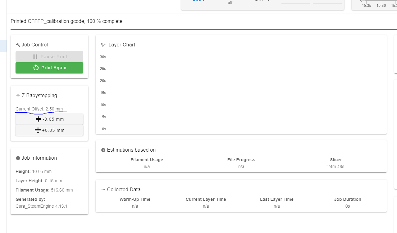
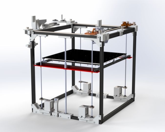
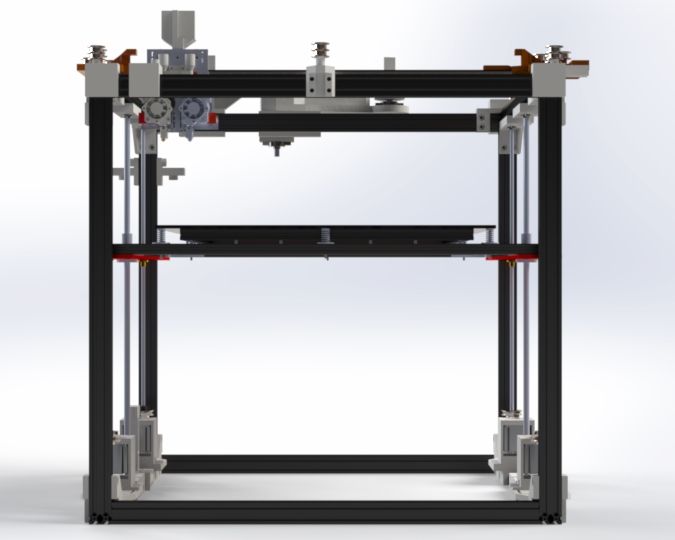
I think I see what you mean. The height that the z probe records will always be 4.1mm however this is somewhat intended. The printer looks like the images below and the bl touch is basically being a limit switch. The plate moves up until the BL touch is triggered and then this is 4.1mm. Maybe the easiest thing is to tweak the 4.1mm in the config file, but this is not so ideal.
But I was thinking I could use the setting below to compensate this 4.1mm but it is forgotten with each new print.
-
@feynman137 The Z offset is set using Z parameter of G31. When you use G30 S-1 you are actually asking the firmware to measure and report that offset.
To probe the bed, you have to use G30: https://docs.duet3d.com/User_manual/Reference/Gcodes#g30-single-z-probe -
I will try this although I am confused as to why I cannot use G30 S-2 instead of G30 S-1.
But if I understand correctly when I issue G31 P500 Z2.6 for example at the instance the bl touch is triggered, the z axis height will be 2.6mm? Also is p500 correct for me?
Also I tried G31 P1000 Z4.3 and the bed moved down not up to meet the BL touch
Even G30 S-2 moves the plate down instead of up.
-
@feynman137 G31 shouldn't move the bed, G30 will and changing the Z probe settings with G31 will not change the axis direction.
If your Z axis move the wrong direction when using G30, you may probably need to fix the axis direction (S value of M569 for the Z driver). But the direction shouldn't have changed since using G30 S-1 ...
-
@Feynman137
@falcounet said in Printer forgetting z-offset at start of new print:If your Z axis move the wrong direction when using G30, you may probably need to fix the axis direction (S value of M569 for the Z driver).
That is most unlikely the cause, since he can print several parts in a row.
I guess it's a false Z-endstop-definition? Z homing to min-endstop is the way to go. -
M558 F100				;adjust zprobing speed
G30 S-1        			; move Z down stopping at the endstop
G92 Z4.1				;set zaxis to z probe trigger height
G1 Z5 F100				;move build plate down slowly for second pass
M558 F10				;adjust zprobing speed to slow
G30 S-1					;zhoming second pass
G92 Z4.1				;set z coordinates
This is a very strange way to do Z homing. Why aren't you just using a G30?
-
What do you mean, I can just use G30 S-1?
Will my printer just use the offset in the config.g file?
-
G30 S-1 is typically used to measure your probe offset.
G92 Z would be used to force a certain position, which kind of defeats to purpose of the probe.
Use a single G30 to probe, and you're good to go.
https://docs.duet3d.com/en/User_manual/Machine_configuration/Configuration_cartesian#homing-z
https://docs.duet3d.com/en/User_manual/Connecting_hardware/Z_probe_testing