Drylin or Not
-
I suspect that my post referred to by @sonderzug relates to the X axis construction I used in my sand table called Arrakis. It uses PTFE blocks sliding in t-slot for the Y axis bearings. The Y axis PTFE bearing at one end of the X axis is fixed to the bearing block and the X axis guide rail. At the other end of the X axis the Y axis bearing block has a PTFE bearing mounted on pins and spring loaded so that the X axis doesn't shift along its length between the Y axis rails when the machine is operating.
Post is here: https://drmrehorst.blogspot.com/2021/10/arrakis-this-is-part-of-weirding-way.html
Prior to spring loading the bearing the whole X axis would shift with an audible "klunk" every time the magnet carriage reversed direction along the X axis rail. The problem was that the belt tension was causing the 45 mm square t-slot Y axis rails/frame members to bow, resulting in a loose fit near the center of the table. Spring loading the bearing solved the axis shifting and noise problem.
-
@dizzwold I'm in Cologne, Germany. On one hand, I think these considerations are valuable for everyone thinking about using drylin, on the other hand I want to point out that my suggestions represent my personal opinion and are not to be mistaken for a manufacturer's recommendation (and I'm not knowledgeable enough to acutally present such a one).
I've just now taken a look at the Tronxy printer you mention. No, I don't think drylin T would be the most suited, price is one thing but I'd recommend it as the easiest solution when replacing "Hiwin-Style" (for lack of a better word in our 3D printing universe) linear rails, because they have the same overall mounting dimensions.
Seeing that the Tronxy printer has those "rod-mounted-to-extrusion" style of linear rails with roller bearings, AND they're at the same time a structural component, I'm actually not sure what to do, it seems like a very involved redesign. If I were to choose components to loosely replicate what Tronxy has designed here, I'd go as follows:
- drylin W rails for the y-axis, e.g. left and right (WS-10 single rail). Mounted horizontally. The beauty of this is that you can choose between a range of bearing blocks to match, e.g. with or without (adjustable) pre-tension, or even as a hybrid roller-slider bearing configuration. The rail can be bought without holes, and it could be bored and/or tapped manually to allow mounting of the z-axis rails.
- I recommend two blocks on each side, adjustable on one and standard on the other, this should already fulfill the fixed/floating bearing requirement - seeing that we don't have much elevated temperatures. It should work to repurpose the plates that come with the Tronxy printer.
- the height of the belt arrangement might change, so it might be neccessary to adjust the motor mounts.
- for the x-axis, the easiest and at the same time possibly cheapest and probably still best solution (in terms of precision, play, weight), could be to redesign it entirely, using two parallel 10 mm steel rods (drylin R) and matching bearings.
- these might be, depending on your machining or manufacturing capabilities, bearings that replicate round linear ball bearings with aluminium case, e.g. RE7UM-01 - this should be the easiest solution again. They are available with tighter tolerances or in a split version that's easy to mount (not both, unfortunately - I'd go for precision over ease of maintenance). 3 or 4 such bearings should be used, compare how Prusa does it.
OK, I think that is all I can contribute to this. If you really decide to go down this route, please contact a sales rep at igus UK, if questions arise reference this thread.
@mrehorstdmd (couldn't remember your handle - drmrehorst? digitaldentist? mrehorstdmd it is
 ) thanks for your input, this wasn't the post I was looking for but it should be relevant nonetheless. I was referring to your method of mounting the floating side of the x axis to another bearing block that is fixed to the carriage, a perfect rendition of a fixed/floating setup...
best, Niklas
-
Thank you for your thoughts.
I'm planning on removing the current Y axis rails and fitting with new 2020 extrusion.
The X & Y motors, belts and idlers are all going to have to be repositioned/raised to accommodate a new rail system to some degree anyway.
-
@sonderzug Oh, I see! I did that because I had read reports of people's linear-guide-based corexy printers that would seize up when the temperature in their shop varied a few 10s of degrees. I intended to heat the machine to 50C for printing ABS, so I wanted to ensure the mechanism would keep moving. Here's a photo of the mechanism when I first put it together.
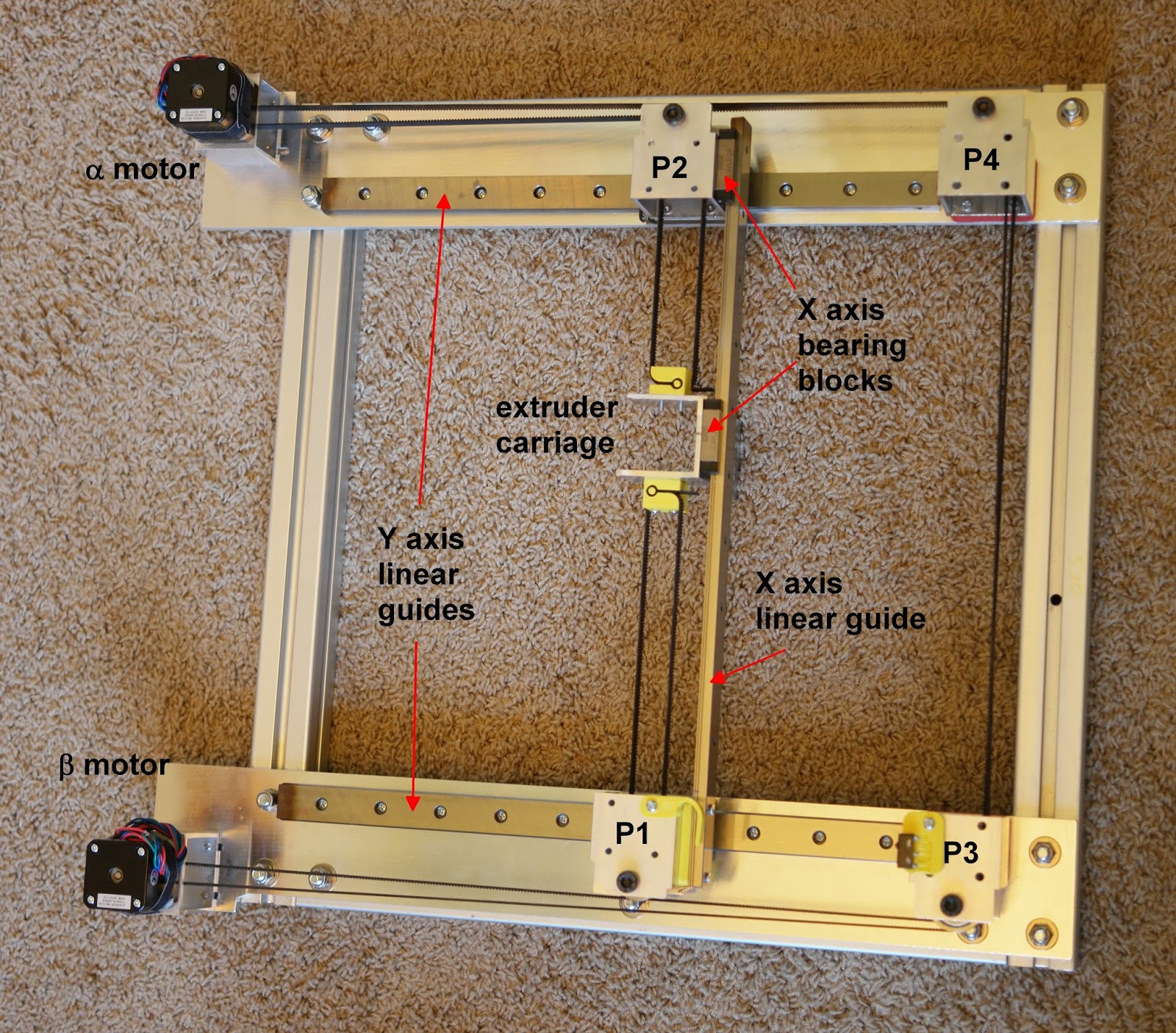
There have been several changes over the last 5 years, but the X axis bearing block at P2 hasn't changed and never will. That extra block allows the Y axis rails to move apart when the machine is heated, which prevents the mechanism from binding.
-
@sonderzug Is there a reason you why you wouldn't go with the T type for the X and Y axis rails?
Here's what I'm preposing to do, some of this is from Ed Palisoc/Daivd Husolo (BLV Cube), and the X gantry Mod is from Havoc340 (awaiting his reply to be able to use his mod);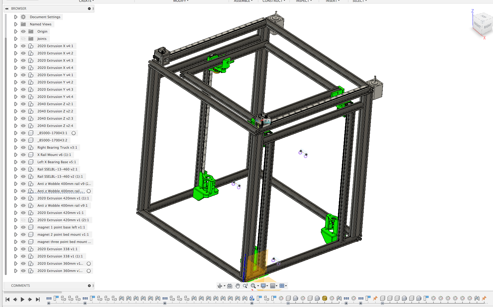
https://www.dropbox.com/s/k5njwtd9fp5njb0/Tronxy Frame v25.f3d?dl=0
-
@Dizzwold Hi, for the y-axis you can probably do this. The TWE-04-12 + TS-04-12 are suitable, and can be adjusted in play. However I'm not 100 % confident that in this configuration, there isn't any rotational play around the x-axis. If you want to use T for the x-axis, I recommend two rails on a 20x20 profile to eliminate play (can be opposite sides or 90° offset, e.g. top and front facing sides of the profile).
Please note that I haven't tested this, which is why I'm a little cautious here...
-
Hi sonderzug,
So for the 2 Y axis rails I would need the 1x, TK-04-12 TWE-1, xxx (no float bearing), and 1x, TK-04-12 TWE-1, xxx, LLY (Y axis float bearing)?
Regarding the X axis Rail. Wouldn't a single rail with a float bearing in the Z axis possibly eliminate any rotation as this could be checked and adjusted when needed?
-
@Dizzwold since the TWE can be adjusted in all directions separately I wouldn't do one floating bearing, but two non-floating. Seeing it's an open frame and the x-axis is probably max. 500-600 mm long, it should work out with the tenths of millimeters of adjustability in the bearing blocks to eliminate binding.
Don't really understand your point about the x-axis rail, my suggestion still stands.
-
Thank you for your advice.
What I was suggesting about the X axis rail is if the possible rotation is like in the image, would the adjustment available in the carriage/bearing block be able to compensate for this?
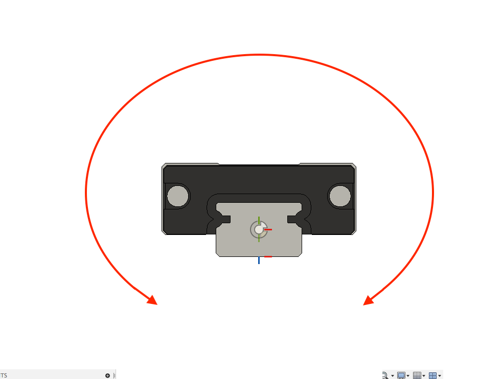
That is, if I've understood you correctly?
-
@Dizzwold oh, I see. No, I don't think this rotational play can be eliminated by adjusting the bearing block. The problem is that between its point of rotation and the tip of the nozzle, a minimal amount of play in the bearing will be amplified to become really problematic.
I'd do it like this:
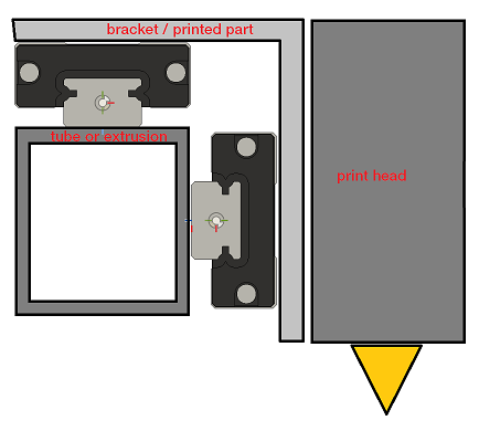
the bracket or printed part can be installed without problems, it doesn't have to have too tight tolerances since the mount is not overconstrained. And wobble in the nozzle is minimized because there is no rotation like in your sketch.
-
Ok. I'm very grateful for your help.