Duet3D Logo Duet3D
    • Tags
    • Documentation
    • Order
    • Register
    • Login
    1. Home
    2. Dizzwold
    • Profile
    • Following 1
    • Followers 0
    • Topics 40
    • Posts 286
    • Best 17
    • Controversial 0
    • Groups 0

    Dizzwold

    @Dizzwold

    20
    Reputation
    17
    Profile views
    286
    Posts
    0
    Followers
    1
    Following
    Joined Last Online

    Dizzwold Unfollow Follow

    Best posts made by Dizzwold

    • RE: Possible corrupt sd card, G29 Network Error

      @jay_s_uk

      Thank you.

      I've also just noticed something in my config.g that I thick, with looking in the dictionary ,is causing conflict. In M950 shouldn't my bed heater be H0 (H zero), rather than T0 (T zero), and my nozzle be T0 (T zero) instead of T1?

      ; Configuration file for Duet 3 MB 6HC (firmware version 3.3)
      ; executed by the firmware on start-up
      ;
      ; generated by RepRapFirmware Configuration Tool v3.3.13 on Mon Sep 19 2022 16:04:20 GMT+0100 (British Summer Time)
      
      ; General preferences
      M575 P1 S1 B57600                                  ; enable support for PanelDue
      G90                                                ; send absolute coordinates...
      M83                                                ; ...but relative extruder moves
      M550 P"Duet 3"                                     ; set printer name
      M669 K1                                            ; select CoreXY mode
      
      ; Network
      M552 P
      
      ; Bed Leadscrew Positions
      M671 X5:278 Y146:146 P2.0						; middle left, middle right
      
      G4 S1												;wait for expansion boards to start
      
      ; Drives
      M569 P0.0 S0                                       ; physical drive 0.0 goes backwards
      M569 P0.1 S0                                       ; physical drive 0.1 goes backwards
      M569 P0.2 S1                                       ; physical drive 0.2 goes forwards
      M569 P0.3 S1
      M569 P121.0 S0                                       ; physical drive 0.3 goes forwards
      M584 X0.0 Y0.1 Z0.2:0.3 E121.0                           ; set drive mapping
      M350 X16 Y16 Z16 E16 I1                            ; configure microstepping with interpolation
      M92 X80.00 Y80.00 Z400.00 E333.40                  ; set steps per mm
      M566 X900.00 Y900.00 Z60.00 E120.00                ; set maximum instantaneous speed changes (mm/min)
      M203 X6000.00 Y6000.00 Z180.00 E1200.00            ; set maximum speeds (mm/min)
      M201 X500.00 Y500.00 Z20.00 E250.00                ; set accelerations (mm/s^2)
      M906 X900 Y900 Z900 E800 I30                       ; set motor currents (mA) and motor idle factor in per cent
      M84 S30                                            ; Set idle timeout
      
      ; Axis Limits
      M208 X-2 Y-8 Z0 S1                                 ; set axis minima
      M208 X330 Y330 Z400 S0                             ; set axis maxima
      
      ; Endstops
      M574 X1 S1 P"!121.io1.in"                              ; configure switch-type (e.g. microswitch) endstop for low end on X via pin !io1.in
      M574 Y1 S1 P"!io2.in"                              ; configure switch-type (e.g. microswitch) endstop for low end on Y via pin !io2.in
      
      
      ; Z-Probe
      M574 Z1 Z1 S2									   ; set endstops controlled be probe
      M558 P8 C"^!121.io0.in" H5 F120 T6000                 ; set Z probe type to switch and the dive height + speeds
      G31 P500 X-46 Y-19 Z2.45                            ; set Z probe trigger value, offset and trigger height
      M557 X19:244 Y-2:304 P9                           ; define mesh grid
      
      ; Heaters
      M308 S0 P"temp0" Y"thermistor" T100000 B4138       ; configure sensor 0 as thermistor on pin temp0
      M950 H0 C"out0" T0                                 ; create bed heater output on out0 and map it to sensor 0
      M307 H0 R0.187 K0.192:0.000 D1.89 E1.35 S1.00 B0   ; disable bang-bang mode for the bed heater and set PWM limit
      M140 H0                                            ; map heated bed to heater 0
      M143 H0 S120                                       ; set temperature limit for heater 0 to 120C
      M308 S1 P"121.temp0" Y"thermistor" T100000 B4138       ; configure sensor 1 as thermistor on pin temp1
      M950 H1 C"121.out0" T1                                 ; create nozzle heater output on out1 and map it to sensor 1
      M307 H1 R2.498 K0.275:0.349 D6.79 E1.35 S1.00 B0 V24.0  ; disable bang-bang mode for heater  and set PWM limit
      M143 H1 S280                                       ; set temperature limit for heater 1 to 280C
      
      ; Fans
      M950 F0 C"121.out1" Q500                               ; create fan 0 on pin out4 and set its frequency
      M106 P0 C"Print Cooler" S0 H-1                     ; set fan 0 name and value. Thermostatic control is turned off
      M950 F1 C"121.out2" Q500                               ; create fan 1 on pin out5 and set its frequency
      M106 P1 C"Extruder Cooling" S1 H1 T45              ; set fan 1 name and value. Thermostatic control is turned on
      
      ; Tools
      M563 P0 S"Hemera" D0 H1 F0                         ; define tool 0
      G10 P0 X0 Y0 Z0                                    ; set tool 0 axis offsets
      G10 P0 R0 S0                                       ; set initial tool 0 active and standby temperatures to 0C
      
      ; Custom settings are not defined
      ; Emergency Stop
      M950 J1 C"io4.in"
      M851 P1 T0 S0 R0
      
      
      ; Miscellaneous
      M911 S10 R11 P"M913 X0 Y0 G91 M83 G1 Z3 E-5 F1000" ; set voltage thresholds and actions to run on power loss
      
      T0
      
      M501
      

      Screen Shot 2022-11-09 at 15.51.43.png

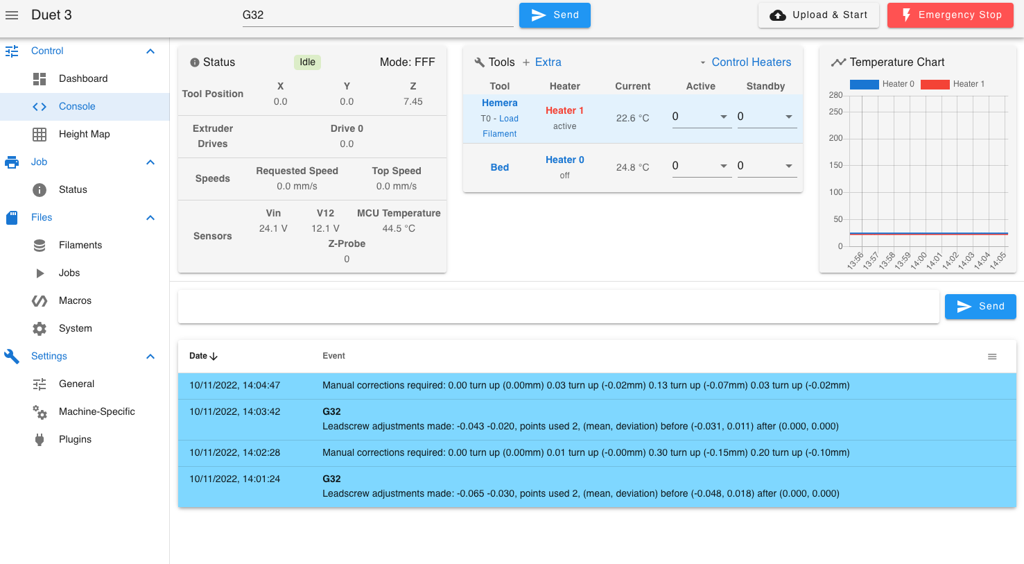
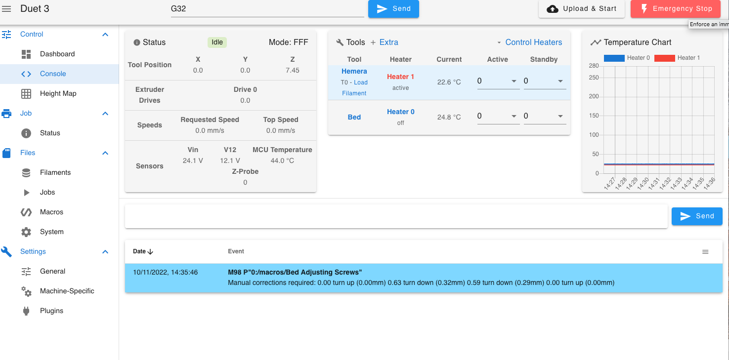
      So far so good with using the ethernet, and without fully commissioning I ran a G32 once with no problems, no running a second scan for unknown reasons and no network error.
      Without further testing I can't say if this was linked to the previous board, found to have an sd card issue or not.

      Sorry "I thick" , * I think.

      posted in General Discussion
      Dizzwoldundefined
      Dizzwold
    • RE: NPN Inductive Z Probe

      @norder

      Thank you for your detailed guidance. I've tinkered with your example code, but not had a good chance to test it (I've got a lot on at the minuet).
      I have had to omit the G92 Z0 in the homez as this resets the the settings previously entered for the trigger height in config.g.
      I appreciate you have different z probes, and what you've sent above is an example. Thank you, It does help a lot.

      I'll try and get time to test/tinker/play tomorrow, but it may be at the weekend until I get good chance to do so.

      Dizzwold.

      posted in Tuning and tweaking
      Dizzwoldundefined
      Dizzwold
    • RE: Hotend 100˚ less on ToolBoard?

      @Dizzwold

      Yep, a clone Toolboard and clone Hemera.

      I'm disabled, and on UK benefits due to health, so after purchasing the original and authentic Duet3 6HC, I couldn't afford the authentic Toolboard or Hemera, so please don't hold that against me. I will over time manage to afford these as original products.

      posted in Tuning and tweaking
      Dizzwoldundefined
      Dizzwold
    • RE: Max distance for control board from machine?

      @mandragora @Norder @jay_s_uk @deckingman ,

      Thank you guy's, these are all very informative and valued information. This give me a lot to consider, and decide upon which way to go with this.

      I've added a photo below. Sorry, I should have done this in first post so you all had a better understanding.

      @Norder I already have a second floor/partition, but this directly above the "built-in" soundproof chamber. I was planning on using this as my filament storage. When I say built-in, it's breeze blocks and plaster. I've already had to strap one side with an addition joist in the loft to take the extra weight of the TecSound soundproofing and soundproof plasterboard as this was unsupported and above a stair case (it did have small notched joist, but not enough for the addition weight).
      wNMNvJxHR8ygYCm57W++ng.jpg
      I'll have to take some temperature reading in the partition above. I suppose I could have it in an enclosure (in the above partition), and have a fan and duct in the timber above the door if needed. Then run cables to the paneldue, that will hopefully sit to the right of the door on the cable trunking.

      Thank you again guy's for your time and advice.

      posted in General Discussion
      Dizzwoldundefined
      Dizzwold
    • RE: Flashing firmware on Mac OS X

      @droftarts

      Hi Ian,

      Thank you again for your help and input.

      I figured the above out in the end (or I hope I have).

      Here is my example from the terminal. Maybe this will help others.

      Mrxxxx's-imac:~ $ bossac -e -w -v -b -R -p /dev/tty.usbmodemFD131 /Users/Mrxxxx/Downloads/PanelDueFirmware-logo-3.4.1-v3-7.0.bin 
      Erase flash
      
      Done in 1.302 seconds
      Write 218036 bytes to flash (426 pages)
      [==============================] 100% (426/426 pages)
      Done in 7.088 seconds
      Verify 218036 bytes of flash
      [==============================] 100% (426/426 pages)
      Verify successful
      Done in 5.581 seconds
      Set boot flash true
      Mrxxxx-imac:~ $ 
      

      Thank you for your help.

      One happy smily bunny.

      posted in Firmware installation
      Dizzwoldundefined
      Dizzwold
    • RE: NPN Inductive Z Probe

      @norder

      Thank you again for your help, I'm very grateful.

      I'll have a look at the home all and homez files.

      @norder said in NPN Inductive Z Probe:

      This is not necessary because the G29 command that does the MeshBedLeveling has already calculated this offset.

      I'd been advised in a previous thread that this wasn't calculated and had to allow for this myself, but was also told that the probe would just report "Unreachable", and continue.

      I'll go and look at the files and see what I can do.

      posted in Tuning and tweaking
      Dizzwoldundefined
      Dizzwold
    • RE: Possible corrupt sd card, G29 Network Error

      @jay_s_uk

      Seriously, a big Thank you for your help @jay_s_uk .

      I'm really grateful for your time and guidance.

      posted in General Discussion
      Dizzwoldundefined
      Dizzwold
    • RE: Considering Duet3, New to RPi

      Hi All,

      So it looks like I'm swaying toward the Duet 3 Mini 5 as few have commented on. This way I can also upgrade ‘if and when’ needed.

      It looks like I'll have to wait a few weeks before any more Duet 3 Mini 5's are ready, No Pressure David. LOL

      I am most grateful for everyone's input and advice.

      No doubt I'll be back again with yet more questions, but for now I think I have a bit of reading to do, to familiarise myself better with the Duet system.

      Also any more comments and / or suggestions are very welcome.

      Thank you,

      Dizzwold.

      posted in Using Duet Controllers
      Dizzwoldundefined
      Dizzwold
    • RE: Twin Z axis Motors and MBLA

      @jay_s_uk @Phaedrux

      Hi Guys,

      I had just written a reply stating that I still hadn't quite figured it out, but I think I've kind-of grasp both your ideas, although they need tidying up they both work;
      Screen Shot 2022-11-10 at 14.05.08.png

      Bed.g

      ; bed.g
      ; called to perform automatic bed compensation via G32
      ;
      ; generated by RepRapFirmware Configuration Tool v3.3.13 on Mon Sep 19 2022 16:04:20 GMT+0100 (British Summer Time)
      ;M561 ; clear any bed transform
      ;G29  ; probe the bed and enable compensation
      M671  X5:278 Y146:146 P2.0
      G28			; home
      G30 P0 X5 Y146 Z-9999				; probe front left
      G30 P1 X278 Y146 Z-9999	S2		; probe front right
      G1  X0 Y0 F12000
      ;G28
      M671 X5:278:278:5 Y5:5:302:302 P0.5
      G28
      G30 P0 X5 Y5 Z-9999				; probe front left
      G30 P1 X278 Y5 Z-9999			; probe front right
      G30 P2 X278 Y302 Z-9999			; probe rear right
      G30 P3 X5 Y302 Z-9999 S4  		 ;probe rear left
      G1  X0 Y0 F12000
      

      Config.g

      ; Configuration file for Duet 3 MB 6HC (firmware version 3.3)
      ; executed by the firmware on start-up
      ;
      ; generated by RepRapFirmware Configuration Tool v3.3.13 on Mon Sep 19 2022 16:04:20 GMT+0100 (British Summer Time)
      
      ; General preferences
      M575 P1 S1 B57600                                  ; enable support for PanelDue
      G90                                                ; send absolute coordinates...
      M83                                                ; ...but relative extruder moves
      M550 P"Duet 3"                                     ; set printer name
      M669 K1                                            ; select CoreXY mode
      
      ; Network
      M552 Pxxx.xxx.xxx.xxx
      
      ; Bed Leadscrew Positions
      M671 X5:278 Y146:146 P2.0						; middle left, middle right
      M671 X5:278:278:5 Y5:5:302:302 P0.5
      
      G4 S1												;wait for expansion boards to start
      
      ; Drives
      M569 P0.0 S0                                       ; physical drive 0.0 goes backwards
      M569 P0.1 S0                                       ; physical drive 0.1 goes backwards
      M569 P0.2 S1                                       ; physical drive 0.2 goes forwards
      M569 P0.3 S1
      M569 P121.0 S0                                       ; physical drive 0.3 goes forwards
      M584 X0.0 Y0.1 Z0.2:0.3 E121.0                           ; set drive mapping
      M350 X16 Y16 Z16 E16 I1                            ; configure microstepping with interpolation
      M92 X80.00 Y80.00 Z400.00 E333.40                  ; set steps per mm
      M566 X900.00 Y900.00 Z60.00 E120.00                ; set maximum instantaneous speed changes (mm/min)
      M203 X6000.00 Y6000.00 Z180.00 E1200.00            ; set maximum speeds (mm/min)
      M201 X500.00 Y500.00 Z20.00 E250.00                ; set accelerations (mm/s^2)
      M906 X900 Y900 Z900 E800 I30                       ; set motor currents (mA) and motor idle factor in per cent
      M84 S30                                            ; Set idle timeout
      
      ; Axis Limits
      M208 X-2 Y-8 Z0 S1                                 ; set axis minima
      M208 X330 Y330 Z400 S0                             ; set axis maxima
      
      ; Endstops
      M574 X1 S1 P"!121.io1.in"                              ; configure switch-type (e.g. microswitch) endstop for low end on X via pin !io1.in
      M574 Y1 S1 P"!io2.in"                              ; configure switch-type (e.g. microswitch) endstop for low end on Y via pin !io2.in
      
      
      ; Z-Probe
      M574 Z1 Z1 S2									   ; set endstops controlled be probe
      M558 P8 C"^!121.io0.in" H5 F120 T6000                 ; set Z probe type to switch and the dive height + speeds
      G31 P500 X-46 Y-19 Z2.45                            ; set Z probe trigger value, offset and trigger height
      M557 X19:244 Y-2:304 P9                           ; define mesh grid
      
      ; Heaters
      M308 S0 P"temp0" Y"thermistor" T100000 B4138       ; configure sensor 0 as thermistor on pin temp0
      M950 H0 C"out0" T0                                 ; create bed heater output on out0 and map it to sensor 0
      M307 H0 R0.187 K0.192:0.000 D1.89 E1.35 S1.00 B0   ; disable bang-bang mode for the bed heater and set PWM limit
      M140 H0                                            ; map heated bed to heater 0
      M143 H0 S120                                       ; set temperature limit for heater 0 to 120C
      M308 S1 P"121.temp0" Y"thermistor" T100000 B4138       ; configure sensor 1 as thermistor on pin temp1
      M950 H1 C"121.out0" T1                                 ; create nozzle heater output on out1 and map it to sensor 1
      M307 H1 R2.498 K0.275:0.349 D6.79 E1.35 S1.00 B0 V24.0  ; disable bang-bang mode for heater  and set PWM limit
      M143 H1 S280                                       ; set temperature limit for heater 1 to 280C
      
      ; Fans
      M950 F0 C"121.out1" Q500                               ; create fan 0 on pin out4 and set its frequency
      M106 P0 C"Print Cooler" S0 H-1                     ; set fan 0 name and value. Thermostatic control is turned off
      M950 F1 C"121.out2" Q500                               ; create fan 1 on pin out5 and set its frequency
      M106 P1 C"Extruder Cooling" S1 H1 T45              ; set fan 1 name and value. Thermostatic control is turned on
      
      ; Tools
      M563 P0 S"Hemera" D0 H1 F0                         ; define tool 0
      G10 P0 X0 Y0 Z0                                    ; set tool 0 axis offsets
      G10 P0 R0 S0                                       ; set initial tool 0 active and standby temperatures to 0C
      
      ; Custom settings are not defined
      ; Emergency Stop
      M950 J1 C"io4.in"
      M851 P1 T0 S0 R0
      
      
      ; Miscellaneous
      M911 S10 R11 P"M913 X0 Y0 G91 M83 G1 Z3 E-5 F1000" ; set voltage thresholds and actions to run on power loss
      
      T0
      
      M501
      

      *Nb, I've omited M98 P"Bed_Adjusting_Screws.g" from bed.g.
      Screen Shot 2022-11-10 at 14.35.54.png
      Bed Adjusting Screw Macro

      G28
      M671  X5:278:278:5 Y5:5:302:302 P0.5
      G30  P0 X5 Y5 Z-9999				; probe front left
      G30  P1 X278 Y5 Z-9999			; probe front right
      G30  P2 X278 Y302 Z-9999			; probe rear right
      G30  P3 X5 Y302 Z-9999 S4  		 ;probe rear left
      G1   X0 Y0 F12000
      

      So it looks like I've learnt more than I even expected today.

      Now I'll try the bed pid again...

      Thank you both again for your help, I'm really grateful. You have the patience of saint's.

      posted in Tuning and tweaking
      Dizzwoldundefined
      Dizzwold
    • RE: 8mm Cast Tool Plate Design Advice

      @jay_s_uk

      The thought I had was to use 6mm deep magnet and leave 2mm on top, but with your failure it maybe best just to go with the large PEI sheet.

      As @deckingman has previously commented and written-up on, and currently uses, you can always use a glass plate on top.

      posted in General Discussion
      Dizzwoldundefined
      Dizzwold

    Latest posts made by Dizzwold

    • 5V on io3.in

      Hi Guys,

      While I'm in the process of building a frame for all my electronics I'm looking at PS_ON.

      I have the Duet 3 6HC and I'm planning on using the following wiring, but -;
      https://forum.duet3d.com/assets/uploads/files/1578482787994-duet-ps_on-wiring.jpg
      Screenshot 2025-03-13 at 16.50.34.png

      -where the switch is in the diagram, I'm going to have a 5 v relay controlled by a switch. A bit of a queer setup I know, having a relay control a relay.
      Now on-top of that, I'd like to use DHusolo's trigger script/code for short press to power On, long press to power Off;
      https://github.com/armysolo/Duet-PS_ON/blob/main/README.md
      AS the switch I'l be using is 5v, controlling the 5v relay, can I input this same 5v into io3.in as the trigger rather than the usual gnd / ioX.in?

      Now your asking why am I doing this when I could have an external 5v powering the duet and simply have ioX.in / gnd connected to a switch with the trigger script/code.

      I don't want the Paneldue being on until the 24v side of the system in on. I only want the 5v & 12v PSU running all the time for lighting, then when I press the switch everything then switches on.
      I appreciate I've created lots of extra work in doing this, but due to the physical positioning of the electronics, printer and personal situation I also don't wish to have a 240v switch as in the original wiring diagram above.

      So basically can I safely short the 5v pin to ioX.in for these few seconds?

      posted in Duet Hardware and wiring
      Dizzwoldundefined
      Dizzwold
    • Duet 6hc Panel Wiring Material

      Hi All,

      I'm about to start building a frame for all my electrical, electronics, and wiring.

      What material are people using for the panel to put all this on?

      I've seen things like Mark Rehorst's UMMD @mrehorstdmd where he's used a cream coloured panel (is this some form of Bakelite or polycarbonate)?

      I'd appreciate your feed back.

      posted in Duet Hardware and wiring
      Dizzwoldundefined
      Dizzwold
    • RE: Dead Heater?

      @Phaedrux @Maestro

      @Phaedrux. the heater isn't fully bonded with silicone. It's fully bonded with Permatex Aviation Form-A-Gasket, then High Temperature silicone around most the perimeter overlapping the heater.
      My understanding is the Permatex Aviation Form-A-Gasket can be removed with IPA.

      The smoke which I thought originated from Arcing/melting of the foam/foil backing on the safety sheet persists.

      I'd temporarily rewired everything and reassembled the printer, then found the smoke again, so I tried placing cameras with the build plate in-situ on the printer, but this didn't helped find where the smoke was coming from, other than the back right corner.

      I wired everything up to bench with 2M cables running from the printer in it's enclosure across the floor and onto my work bench.
      Guess what, No smoke???
      Heater worked.

      I'm wondering if it's, when I put the bed assembly on to the printer, I'm accidentally touching the lead screws and getting grease from the lead screws onto the edge of the bed. Then when I heat the bed it's burning off.

      I'm going to have do more investigating, and I've now put some lengths or 20mm plumbing pipe over the lead screws.

      IMG_3890.jpg

      I've also since found this 'plug-in' RCD (buried in the garage). Weather this will be the correct type, at-least it should give some addition protection for the time being.
      IMG_3891.jpg
      IMG_3892.jpg
      I've also ordered some DIN Rail terminals, and I'm going to build an individual wall mounted frame for all the electronics, and electrical, as it's just a tangled mess at the moment.

      posted in Duet Hardware and wiring
      Dizzwoldundefined
      Dizzwold
    • RE: Dead Heater?

      @Maestro

      I think I'm going to have to re-bond the heater to the tool-plate, as I've found a few spots where it's delaminated (like air bubbles/pockets).

      It's only a 4 or 5 spots, and the heater also has layer of High Temperature RTV around parts of the perimeter as an added protection against such, but being as I have the build plate Off and dismantled I may as well take the opportunity.
      Is there anything that will remove 'my silicone' from around the perimeter and not damage the heater silicone?

      Just waiting on some longer bolts to attach the tool-plate to the assembly.

      Something else I've noticed last night was a slightly darkened area around where I suspect the arcing happened.
      I've tried cleaning this with IPA and microfibre cloth but it wont budge.
      The heater still tests at 70.9Ω, so I'm hoping it's only smoke damage and not the heater (no scorching on the topside either).
      I'll just have to test with caution.
      IMG_3851_1.jpg
      IMG_3852.jpg

      posted in Duet Hardware and wiring
      Dizzwoldundefined
      Dizzwold
    • RE: Dead Heater?

      @Maestro

      I have no expatiation as to why the RCD on my fusebox didn't trip, but I think I may have figured out where the smoke was coming from.

      My build plate is assembled as follows;
      Screen Shot 2025-01-04 at 20.30.40.png

      On top of the 2mm aluminium safety sheet is (sandwiched between underside of heater and safety sheet), is the bonded 3mm foam and foil sheet.

      I've just realised everything but this foil sheet is earthed.

      If I run a continuity test across the earthing to the foil sheet I get nothing, but if I press down on the foil sheet roughly where the damaged crimp was (heater cable), I get continuity.

      So at this moment, and I'm only guessing, the smoke was from the foam burning and melting under the bonded foil and shorting the the safety sheet.

      If I was to buy a DIN rail mount RCD which type should I choose A, AC, B, F, S ?

      posted in Duet Hardware and wiring
      Dizzwoldundefined
      Dizzwold
    • RE: Dead Heater?

      @Maestro

      I'm trying to recall my re-wiring and the ground fault interrupt.

      Was it that I stated my Domestic Mains Fusebox has an RCD?

      Which is correct, but yet this hasn't tripped...

      I may invest in RCD protected wall outlet socket.

      posted in Duet Hardware and wiring
      Dizzwoldundefined
      Dizzwold
    • RE: Dead Heater?

      @dc42
      Sorry, I forgot to add the photo of them, but I think you are correct;
      IMG_3848.jpg

      I assume your talking of these;
      Screen Shot 2025-01-05 at 21.10.21.png

      posted in Duet Hardware and wiring
      Dizzwoldundefined
      Dizzwold
    • RE: Dead Heater?

      @dc42 @Phaedrux @deckingman @Maestro

      Hmm,

      I've found the problem and all I can say is;

      Thank You to Everyone on the Forum

      For helping me in checking my wiring before assembling the bed.

      It might have been a different story if not for the help on here;
      IMG_3846.jpg
      IMG_3847.jpg

      The sheathing/case of my crimp connector had been crushed slightly, splitting it open and although there's No scorch marks, it must have been shorting to the foil coated foam on my safety sheet (in-case heater mat adhesive gives up), all of which are Earthed.

      If it wasn't for you guys helping me get my wiring done safely, this short could have been, well I don't think I need to say any-more.

      Tested the heater (less the TCO), and I have 70.9Ω. So all good there.

      Just need to rethink parts of my design now.

      These heat shrink cable connectors/joiners, would these be safe to use on the heater/TCO cables?
      I remember reading somewhere in the documents that it's generally best/safer practice to use physical connections on high current cables rather than solder, as the solder could soften.
      Other than that, I may just have to increase the distance between the heater/tool-plate to the safety sheet to accommodate the crimp connections and maybe a layer of cork or something.

      Again, thank you for keeping me safe from having the correct Earthing and wiring in-place.

      Oh yeah, I should state the blackened stuff around the perimeter of the heater mat is the Permatex Aviation Form-A-Gasket used to bond the heater mat to the tool-plate. It's not scotching or burns.

      posted in Duet Hardware and wiring
      Dizzwoldundefined
      Dizzwold
    • RE: Dead Heater?

      @dc42 @Phaedrux

      The heater is 240vac 800w, so I should get a reading of 72Ω.

      With my multimeter set to 200, 2K, 20K, 2M, 20M, and 200MΩ, I get a 1 on the display (INF). This is on the Live/Neutral cables and Live to Earth, Neutral to Earth.

      I guess it's shafted then.

      Also just tested the bed thermistor with a heat gun to gently heat, and this seems fine.

      posted in Duet Hardware and wiring
      Dizzwoldundefined
      Dizzwold
    • RE: Dead Heater?

      @Phaedrux

      It's a Keenovo style heater 240vac

      The warning was related to not heating quick enough. It was actually cooling in the ambient air when it should have been heating. Is there a way to find the actual warning after I've powered it off?

      I've removed the build plate, but I cant see the heater in full until tomorrow when I fully disassemble the assembly (metal safety sheet and frame).

      Sorry I don't have a current wiring diagram to-hand ( I think it's on an old computer packed away in the loft, I'll try to organise it tomorrow).
      It is basically this diagram, only there is No SSR1, and the 5v PSU is wired directly to the Duet 'EXT 5V'. The Live (hot cable) powering the 24v PSU goes directly to the o/p-side of the SSR2 then onto the heater.
      Screen Shot 2025-01-04 at 20.10.42.png
      Screen Shot 2025-01-04 at 20.30.40.png

      The LED on the SSR switches On when inputting the heater to heat, and when doing so my multimeter goes from an open circuit to 1.9kΩ, so the relay is fine

      The Thermistor for reporting the heater temp is also reporting the ambient room temp (around 22˚c), so I don't think this is an issue.

      I'll have a dig-around tomorrow and see if I can find a current wiring diagram, and take the build plate assembly apart.

      posted in Duet Hardware and wiring
      Dizzwoldundefined
      Dizzwold