Induction probe false triggering
-
-
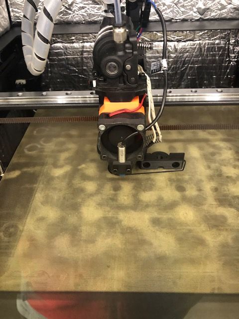
@bubblevisor can you see if having the FAN on or off makes a difference. It looks to me like the probe is mounted right next to the fan motor.
-
@T3P3Tony I was wondering the same thing. Let me do some back to back comparisons and report back.
-
Testing back to back, it does seem the running fan is causing the false triggering problem. I need to test further to better confirm this but I can now complete a bed mesh without errors with the fan off.
My question now is; how can you shield the probe from magnetic flux emanating from the fan? I realise the more obvious solution is to move the probe further away, however I am keen to keep the probe in its position close to the nozzle to reduce error and for packaging reasons.
The stainless probe barrel is non magnetic so I am thinking a mild steel foil around the FINDA probe. Any other ideas?
-
@bubblevisor said in Induction probe false triggering:
Any other ideas?
Turn off the fan during probing.
-
@Phaedrux Thanks for the suggestion. How would you suggest doing this without there being a overheating risk? It seems if you set fan M106 S1 H1 T45 thermistor mode then you cannot overide this in subsequent gcode.
-
I thought I could just change the start gcode to not heat up the hotend until bed mesh is done but I can't see the facility to do this with slicing software. I use prusaslicer.
-
@bubblevisor you have the inductive sensor in the worst possible place relative to the fan, from the point of view of picking up magnetic fields from it. Can you move the sensor sideways, so that it is on one side of the fan or at least lined up with one edge of the fan?
Duet WiFi hardware designer and firmware engineer
Please do not ask me for Duet support via PM or email, use the forum
http://www.escher3d.com, https://miscsolutions.wordpress.com -
@bubblevisor said in Induction probe false triggering:
I thought I could just change the start gcode to not heat up the hotend until bed mesh is done but I can't see the facility to do this with slicing software. I use prusaslicer.
In prusa slicer you must insert your own temperature commands into your start gcode for it to stop inserting it's own preheating commands to the beginning of the files. You can use the placeholder values to insert your chosen temps.
Here is a list of placeholder variables: https://help.prusa3d.com/article/list-of-placeholders_205643 and here https://help.prusa3d.com/article/macros_1775
The first one doesn't seem to be complete for some reason.
Example would be something like
M106 S0 H-1 ; disable hotend fan G28 ; home G32 ; leveling G29 ; mesh M106 S1 H1 T45 ; re-enable temp controlled fan M104 S{first_layer_temperature[0]} ; set first layer temp M116 ; wait for temp -
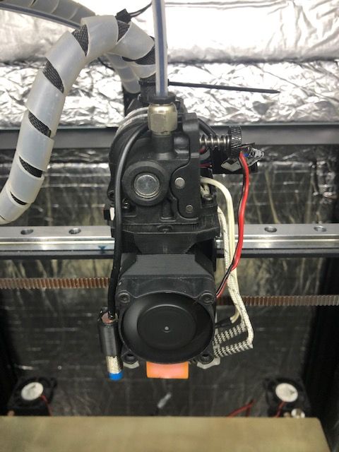
I have changed the induction probe position to ensure no emc noise is reaching from the fan. However I still have z homing and bed mesh issues.I'm beginning to think it a problem with the board. It worked fine when I built the printer over a year ago but lately there have been increasing intermittent issues with the z induction probe "not triggering" or "triggering before move" errors.
Now, the printer won't respond to the tool length micro switch. Bizarrely it now z homes responding to the induction probe. All without me changing the config! What could be going on here??
I have checked the board led is reacting correctly to the tool length probe switch, which it does so fine. Could this really be a faulty board?
-
; Configuration file for Duet WiFi (firmware version 2.03)
; executed by the firmware on start-up
;
; generated by RepRapFirmware Configuration Tool v3.2.3 on Tue Jul 20 2021 13:11:51 GMT+0100 (British Summer Time); General preferences
G90 ; send absolute coordinates...
M83 ; ...but relative extruder moves
M550 P"Saphire" ; set printer name
M669 K1 ; select CoreXY mode; Network
M552 S1 ; enable network
M586 P0 S1 ; enable HTTP
M586 P1 S0 ; disable FTP
M586 P2 S0 ; disable Telnet; Drives
M569 P0 S1 D2 ; physical drive 0 goes forwards
M569 P4 S1 D2 ; physical drive 4 goes forwards
M569 P2 S0 D2 ; physical drive 2 goes forwards
M569 P3 S0 D2 ; physical drive 3 goes forwards
M569 P1 S0 D2
M584 X0 Y4 Z1:2 E3 ; set drive mappingM350 X128 Y128 Z128 E16 I0 ; configure microstepping without interpolation
M92 X640.00 Y640.00 Z6400.00:6400.00 E669.00                  ; set steps per mm
M566 X1000.00 Y1000.00 Z100:100 E520.00 P1               ; set maximum instantaneous speed changes (mm/min)
M203 X20000.00 Y20000.00 Z800.00:800.00 E70000.00            ; set maximum speeds (mm/min)
M201 X20000.00 Y20000.00 Z200.00:200.00 E4000.00            ; set accelerations (mm/s^2)
M906 X1100 Y1100 Z1300 E850 I30 ; set motor currents (mA) and motor idle factor in per cent
M84 S30 ; Set idle timeout; Axis Limits
M208 X0 Y0 Z0 S1 ; set axis minima
M208 X300 Y299 Z340 S0 ; set axis maxima
;M556 S100 X0 Y0 Z0:0:0 ; set skew x.xxmm on 100mm square x-y obtuse; Endstops
M574 X1 S1 P"xstop" ; configure active-high endstop for low end on X via pin !xstop
M574 Y1 S1 P"ystop" ; configure active-high endstop for low end on Y via pin !ystop
M574 Z0 P"nil" ; No Z endstop; Z-Probe
M558 K0 P5 C"^zprobe.in" H2 F1000 T6000 A20 S0.01 ; set Z probe type to effector and the dive height + speeds, max number of probes per point, tolerance(MM)
;M308 S2 P"e1temp" A"PINDA" Y"thermistor" T100000 B3950 ; configure sensor 2 as thermistor on pin e1temp
G31 K0 P1000 X-34.5 Y-13 Z0.18 ;H2 S27 T0.020 ; set Z probe trigger value, xy offset, z trigger height(higher=closer to bed)don't care, temp sensor number, reference temp, compensation coefficient mm/degree(higher more close when hot);Bed Levelling
M671 X4:233 Y170:170 S25 ;leadscrew/pivot locations and max allowable deviation
M557 X10:265 Y5:270 P6:6 ; define mesh grid; Z Tool Length probe
M558 K1 P5 C"^zstop" T8000 F600 H2 A10 S0.01 R0.2 ;set second (K1) Z probe: pin in, travel speed to probe, probing speed, dive height, max number of probes, tolerance(MM), rest time
G31 K1 P500 X0 Y0 Z0.75 ;set second (K1) Z probe: trigger value (higher value = closer nozzle); Heaters
M308 S0 P"bedtemp" Y"thermistor" T100000 B3950 ; configure sensor 0 as thermistor on pin bedtemp
M950 H0 C"bedheat" T0 ; create bed heater output on bedheat and map it to sensor 0
M307 H0 B0 R1.028 C177.2 D6.82 S1.00 ; disable bang-bang mode for the bed heater and set PWM limit
M140 H0 ; map heated bed to heater 0
M143 H0 S120 ; set temperature limit for heater 0 to 120CM308 S1 P"e0temp" Y"thermistor" T100000 B3950 ; configure sensor 1 as thermistor on pin e0temp
M950 H1 C"e0heat" T1 ; create nozzle heater output on e0heat and map it to sensor 1
M307 H1 B0 R2.373 C103.0 D8.21 S1.00 V24.2 ; disable bang-bang mode for heater and set PWM limit
M143 H1 S280 ; set temperature limit for heater 1 to 280CM308 S3 A"Chamber" P"exp.thermistor3" Y"thermistor" T100000 B3950 ; configure sensor 3 as "thermistor" type on pin "thermistor3" (Henry added for chamber monitoring)
; Fans
M950 F0 C"fan0" Q500 ; create fan 0 on pin fan0 and set its frequency
M106 P0 S0 H-1 C"Part cooling fan" ; set fan 0 value. Thermostatic control is turned off
M950 F1 C"fan1" Q500 ; create fan 1 on pin fan1 and set its frequency
M106 P1 S1 H1 T85 C"Heat Break Fan" ; set fan 1 value. Thermostatic control is turned on
M950 F2 C"fan2" Q500 ; create fan 2 on pin fan2 and set its frequency (Henry add chamber fan)
M106 P2 S0 H-1 C"Chamber fan" ; set fan 0 value. Thermostatic control is turned off;LED Lights
M950 P0 C"e1heat"
M42 P0 C"LEDs"; Tools
M563 P0 S"Dragon" D0 H1 F0:1 ; define tool 0
G10 P0 X0 Y0 Z0 ; set tool 0 axis offsets
G10 P0 R0 S0 ; set initial tool 0 active and standby temperatures to 0C; Custom settings are not defined
; Miscellaneous
M575 P1 S1 B57600 ; enable support for PanelDue
M911 S21 R22 P"M913 X0 Y0 G91 M83 G1 Z3 E-5 F1000" ; set voltage thresholds and actions to run on power loss
T0 ; select first tool -
Here's the homez.g
; homez.g
; called to home the Z axis
;
; generated by RepRapFirmware Configuration Tool v3.2.3 on Tue Jul 20 2021 13:11:51 GMT+0100 (British Summer Time)
;G91 ; relative positioning
;G1 H2 Z5 F6000 ; lift Z relative to current position
;G90 ; absolute positioningM98 P"go to z-switch.g"
G30 K1 Z-999 ; home Z by probing the bed via K1
G1 Z5 F2000 ;lift z -
Btw, the board is a duet 2 wifi.
-
@dc42 Could my issue be a board fault? The printer now is completely non responsive to the tool length probe micro switch (that also doubles as Z endstop). Instead it now z end stops via the induction probe. All without me touching the config!. Can this be a board/firmware fault??
-
Can you post the rest of your macros?
@bubblevisor said in Induction probe false triggering:
but lately there have been increasing intermittent issues with the z induction probe "not triggering" or "triggering before move" errors.
This still sounds like interference. Did you investigate turning the fan off during probing?
-
-
@Phaedrux Well, the problem exists even with the fan off. Plus I have moved the probe into a location that should not receive interference from the fan.
The weird thing is I cannot get the printer to react to the tool length probe anymore. This is despite the fact that the z-stop led responds when I press the micro switch.
-
M92 X640.00 Y640.00 Z6400.00:6400.00 E669.00 ; set steps per mm M566 X1000.00 Y1000.00 Z100:100 E520.00 P1 ; set maximum instantaneous speed changes (mm/min) M203 X20000.00 Y20000.00 Z800.00:800.00 E70000.00 ; set maximum speeds (mm/min) M201 X20000.00 Y20000.00 Z200.00:200.00 E4000.00 ; set accelerations (mm/s^2)You only need a single value for the Z axis. Remove the duplicates. Multiple values are only required for extruders.
M574 Z0 P"nil" ; No Z endstopThis is unnecessary and can be removed. Using nil is only required if you need to clear a previously assigned pin. After 3.0 there are no default assignments.What is in the macro "go to z-switch.g"?
;First pass
M558 H10
G30 K0 P0 X265 Y150 Z-99999 ; probe near left leadscrew
G30 K0 P1 X10 Y150 Z-99999 S2 ; probe near right leadscrew and calibrate 2 motors
;Second Pass
M558 H5
G30 K0 P0 X10 Y150 Z-99999 ; probe near a leadscrew, half way along Y axis
G30 K0 P1 X265 Y150 Z-99999 S2 ; probe near a leadscrew and calibrate 2 motors
;Third Pass
M558 H2
G30 K0 P0 X265 Y150 Z-99999 ; probe near a leadscrew, half way along Y axis
G30 K0 P1 X10 Y150 Z-99999 S2 ; probe near a leadscrew and calibrate 2 motors
In your bed.g you may have a problem with the way you are using M558. Since you have multiple probes you must always use K# to tell the firmware which probe you're trying to address.
-
-
@Phaedrux Do you mean I need to fully define M558 in the bed.g as well as in config.g? such as M558 K0 P5 C"^zprobe.in" H10 F1000 T6000 A20 S0.01
THe other point to make is that the printer IS responding fine to the induction K0 probe just fine, but ignoring K1 tool length in favour of the induction probe during homeZ.