5 bar scara on duet3!
-
Re: How Tough is a Scara Arm to Build?
Hey there! It's been a minute! I finally had some time before thanksgiving to get started on this again, and I've got a mostly working prototype ready to show off! I made a quick test script to get it jogging around: https://www.youtube.com/shorts/zrc9WnjuYPw
For now, I'm just plugging it into my old machine as is to borrow the board for testing until I've got it working fully as a printer. The Z axis will follow as soon as I can get the XY motion system working nicely.
Weird thing I'm noticing, it's like the machine is in degrees of rotation at each motor rather than converting to cartesian space. Here's the little script you saw in the short:
G91 G1 H2 X25 F500
G91 G1 H2 Y25 F500
G91 G1 H2 X-25 F500
G91 G1 H2 Y-25 F500G91 G1 H2 X25 F1000
G91 G1 H2 Y25 F1000
G91 G1 H2 X-25 F1000
G91 G1 H2 Y-25 F1000G91 G1 H2 X10 F1000
G91 G1 H2 Y10 F1000
G91 G1 H2 X-10 F1000
G91 G1 H2 Y-10 F1000G91 G1 H2 X25 Y25 F1000
G91 G1 H2 X-25 Y-25 F1000
G91 G1 H2 X25 Y25 F1000
G91 G1 H2 X-25 Y-25 F1000I can only get the machine to move with H2 code in the line, otherwise it throws an error that the position is unreachable. I'm guessing this is due to the machine limits from the M669 setup line? Is there a specific way to move from degrees to inverse kinematics so you can feed the printer cartesian Gcode and it'll interpret the movements to motor movements?
Here's my config file so far, maybe I'm missing something?
M92 X1166.667 Y1166.667 ; set steps/deg - this is pretty close based on some initial testing!
M350 X128 Y128 I1 ; set microstep, with interpolation on
M569 P0 S1 ; Drive 0 (X) goes forwards (left motor)
M569 P1 S0 ; Drive 1 (Y) goes forwards (right motor)
M574 X1 Y1 Z0 S1 ; proximal L and R homing switches trigger when the arm is at M669 B positions and are active high
M669 K9 X0:120 Y0:0 L2 P543.56:543.56 D543.56:543.56:0:0 B65.7:0 A10:160:30:160:30:160 C45:180:0:135
M203 X1000 Y1000 ; maximum speeds deg/minute?
M906 X1200 Y1200 ; set motor currents (mA)
M201 X80 Y80; Endstops
M574 X1 S1 P"!^io0.in" ; configure switch-type (e.g. microswitch) endstop for low end on X via pin io0.in
M574 Y1 S1 P"!^io1.in" ; configure switch-type (e.g. microswitch) endstop for low end on Y via pin io1.inZ-Probe
M950 S0 C"io7.out" ; create servo pin 0 for BLTouch
M558 P9 C"io7.in" H4.75 F240 T12000 ; set Z probe type to bltouch and the dive height + speeds
G31 P500 X-45 Y-30 Z4 ; set Z probe trigger value, offset and trigger height
M557 X20:400 Y20:750 S50 ; define mesh grid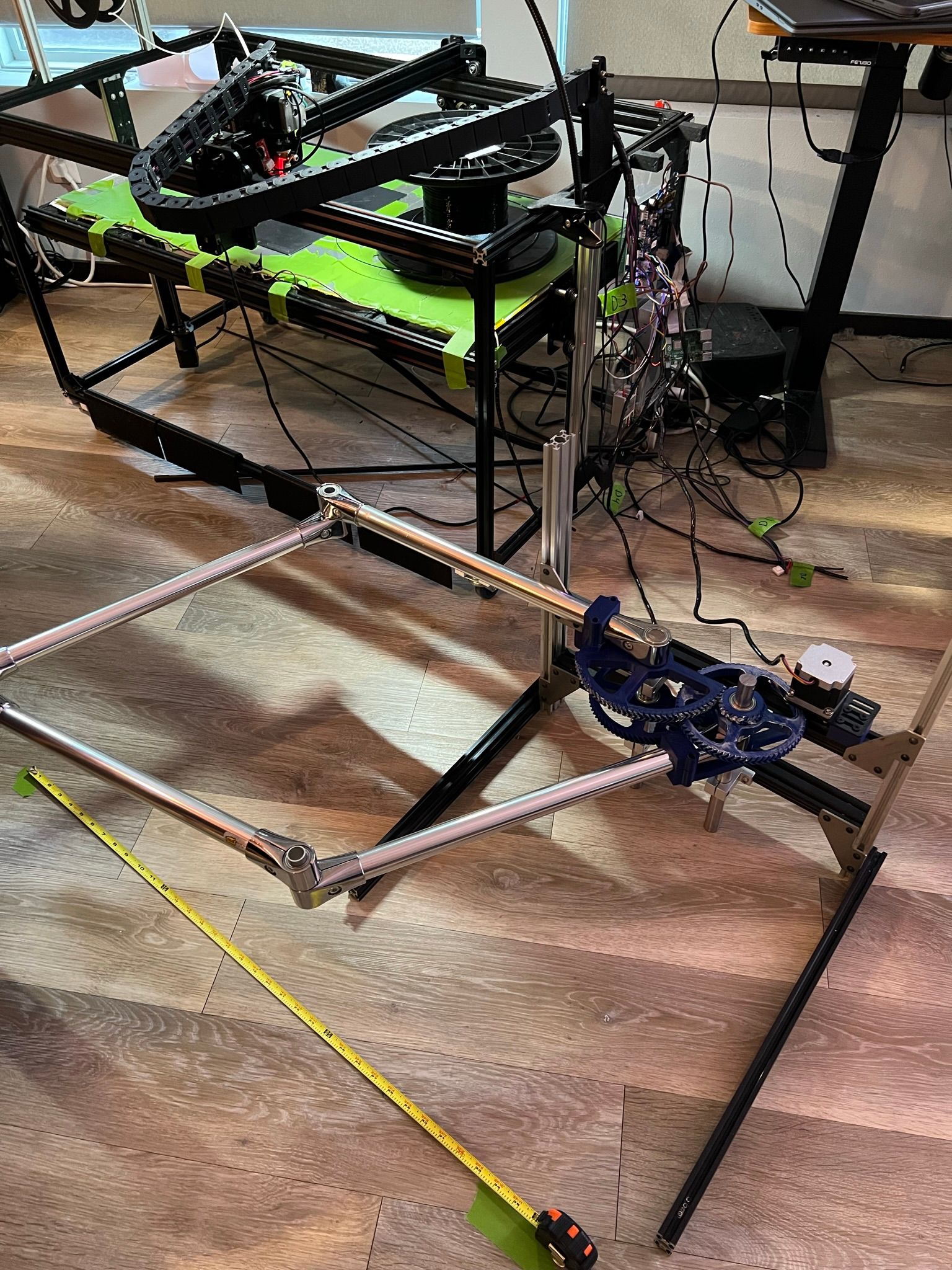
-
@michaelr123 welcome to your try with 5 bar parallel scara.
The documentation is https://docs.duet3d.com/User_manual/Machine_configuration/Configuration_five_bar_parallel_scara with a chapter about homing. I suspect that one of the angle settings is not correct, or the workmode does not fit to the position, and you have to set the M208 limits.
The G1 H2 moves is a special G1 command for single stepper movement. X and Y are rotational axes, so the values are interpreted as degrees. When you use the normal G1, G1 is interpreted as cartesian coordinates.
BTW the parameters like M92 are also degree based, so where you have steps/mm normally, you have steps/degrees now. And where you have mm/min, you have degrees/min for X and Y. Your M92/M201 values are probably wrong.
M92
M201: if you have a 200 step stepper, then the calculation is for one rotation 200 * 16 microsteps / 360 degrees = 8.888 steps/degrees. This low value is an indication that the precision is limited. Gears are often used between stepper and axis to achieve a higher precision/accuracy. A gear's ratio will change the M201 accordingly. In your image you have a gear between stepper's pulley and the big wheel. If it's for example 1:10, then your M92M201value is 88.8888It's best if you activate Z now, because I am not sure whether the code works without it. The kinematics is based on Zleadscrew, which means all methods for Z linear movements like mesh compensation work. But the kinematics will probably assume there is a Z. You can fake Z homing by issuing G92 Z0.
-
@michaelr123 I remembered your name somehow and searched. We had a discussion in March already, so you have some understanding already.
Additionally to my post before, the most probable reason for not reachable is the missing M208.
I confused M201 with M92. M201 is acceleration, but also in degrees instead of mm (so the value is in degrees/s²).
The M92 values seem too high. -
@michaelr123 said in 5 bar scara on duet3!:
M350 X128 Y128 I1
ok; I see why you have such a high M92. It's the high M350 setting. 128 microsteps will produce problems like lost steps. If you set 16 with the I1 setting, Duet 3 will send 16 microsteps to the drivers and the Trinamic driver chips will interpolate them to 256 microsteps. 128 microsteps will not give you more accurancy than 16 mcirosteps.
-
Yep! I made a new forum from March or so now that this will be more of a build log rather than asking if this is a good idea or not. I've had time to noodle on it and come up with a gearing system that was pretty quick and easy to implement. right now it's Nema 23's geared down by 16.4. There's still lots of spring in this system, but I'll transition to something more robust once I'm working a final design. I'm thinking aluminum GT2 belt's and pulleys or maybe I'll find a super low backlash geared steppers to use. The arm system seems to be holding up nicely, though I've found it does sag a bit at it's furthest reach. I'll either need to tilt the bed or the arm to compensate.
good catch on the M350 code I forgot that it's supposed to be 16 I1 rather than 128, I was following one of the examples from the wiki

So you do need an M208 code then? I guess I haven't really calculated a rectangular area for this thing yet. I could drive the motors around and come up with something to start off with as the XY position reported from Duet seems fairly accurate after manually jogging the motors.
I played around with the jerk and accelerations and found it was in deg/sec. Hence the really low M201 number. This was getting me smoother motion as there's still a good amount of spring in the system.
-
@michaelr123 the M208 has two tasks. One is to set the home value to the lower or upper M208 value with a G1 H1. But this is not used here. The second task is the limit and an error if it's violated. So it is safe to set very low minimum and high maximum values.
As for gears, bondus' approach is very nice, because a belt based gear has very few backlash. An alternative is a harmonic drive. I'm currently designing and printing them for my robot project. When I have something, I'll tell it in the forum. Cycloidal drives are an alternative. Planetary drives have more backlash.
The vertical stability is very critical, you're right. Make it as stable as you can.
In your March thread you already used something like vertical constraints. Like my robot approach in https://forum.duet3d.com/topic/17421/robotic-kinematics/112 from Oct 12 2020 where I try to get a stable construction by two parallel arms. Maybe this is an idea for your construction.
My current construction idea is to base every connection on two points: an axis at two ball bearings and extrusion enforcements at two points each for every extrusion side. If possible, no cantilevered construction. The reason is to hinder pivoting and bending.
-
I'm curious how printed cycloidal gear systems will hold up long term. I've found zero backlash on youtube who has done great work with a robotic arm and producing a few different gear boxes that seem to be robust. I'm guessing I'll end on on belts and pulleys. I use them all over my voron and they just work. I'll probably need to print the larger pulleys to get the ratios I'm after and have an ID to fit around the 20mm steel shaft I'm using as the base for the arms. A few sets of 6mm belts will provide the stiffness required to get a nice rigid system. Ultimately, large format machines don't need to move super fast as you just can't melt and cool plastic fast enough to need a higher linear speed, so I think a large, slow moving 5 bar scara is a viable option.
The reason I'm building this machine is to get a larger (taller) build space and also to have a system that can be taken down when not in use. The z rails will stay mounted to the wall, but the arm system will be attached and wired in, the build plate will be brought out from storage, and then run an auto calibration process to get started. It's also just a really cool engineering project
") If it goes well, I'll publish it as a open source plan as it's a super cheap project overall to get into large form printing with ~hopefully~ a robust, high quality motion system. I'll have to add it all up, but the system in that video plus the duet3 is less than $500. Granted there's no extrusion system, z axis, or build plate yet, but that isn't more than a few hundred dollars more.
If it goes well, I'll publish it as a open source plan as it's a super cheap project overall to get into large form printing with ~hopefully~ a robust, high quality motion system. I'll have to add it all up, but the system in that video plus the duet3 is less than $500. Granted there's no extrusion system, z axis, or build plate yet, but that isn't more than a few hundred dollars more.I'll work on this more after thanksgiving celebrations but I'm hopeful this will work well!
-
@michaelr123
If the main reason for building a 5-bar scara is the option to wallmount it, I've seen a video from THE Nicholas Seward with a wall mounted Delta.
Just saying... -
cool idea! I’ve never built or worked with a delta, but it sounds like a cool project for someone!
-
Alright folks, I made some more progress, but I still can't get the machine to accept a small G1 movement. I'm also noticing as I jog a motor in a direction that I would expect it to be increasing X and Y, both are decreasing. The robot may think it's flipped in space somehow?
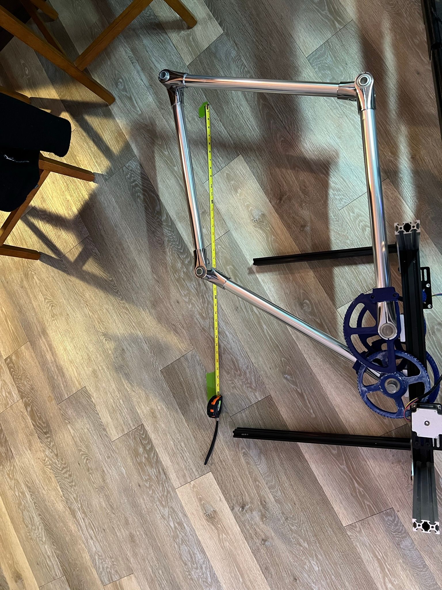
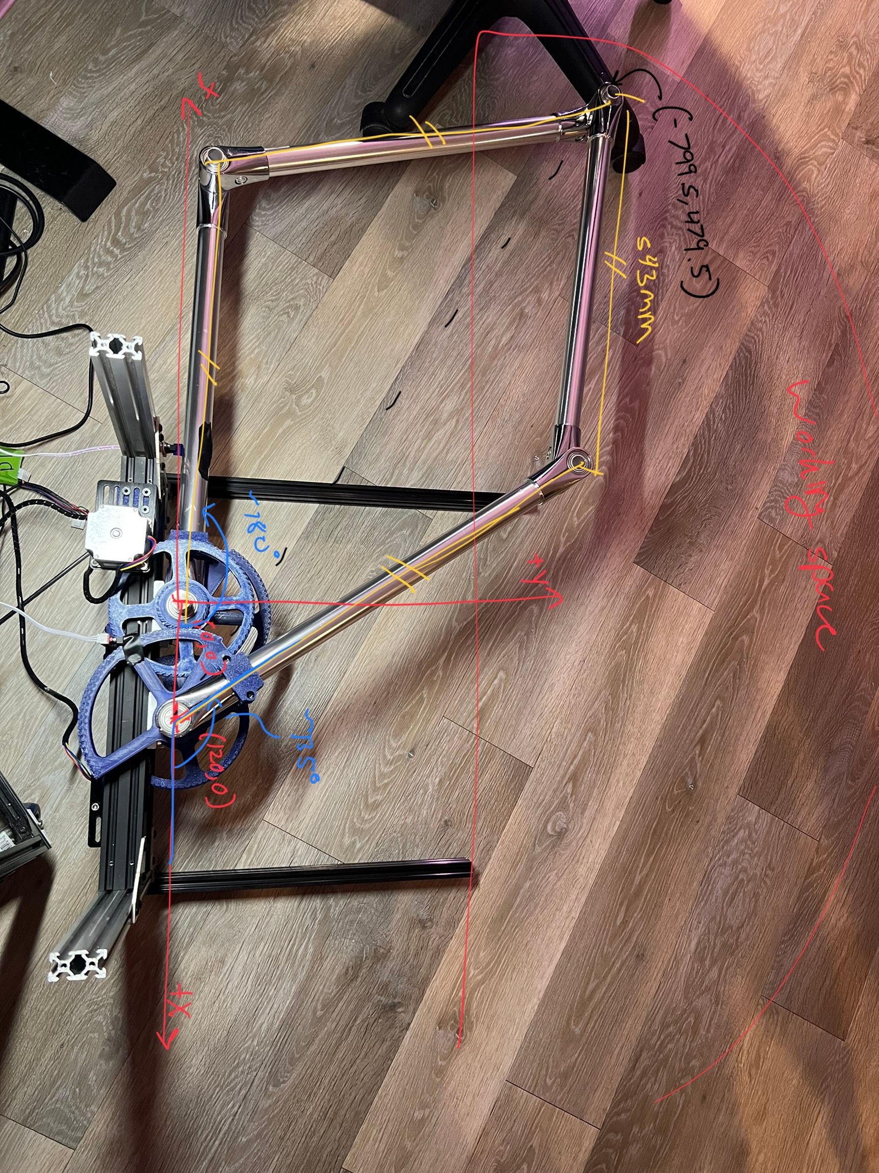
Here's my updated firmware and a picture of the robot so we can overlay the the coordinate system over the top to double check my numbers:
M92 X145.833 Y145.833 ; set steps/deg - this is pretty close based on some initial testing!
M350 X16 Y16 I1 ; set microstep, with interpolation onM569 P0 S0 ; Drive 0 (X) goes forwards (left motor)
M569 P1 S1 ; Drive 1 (Y) goes forwards (right motor)
M574 X1 Y1 Z0 S1 ; proximal L and R homing switches trigger when the arm is at M669 B positions and are active high
M669 K9 X0:120 Y0:0 L2 P543.56:543.56 D543.56:543.56:0:0 B180:135 A0:180:0:180:0:180 C3:170:0:135 Z-1000:0:1000:1000
;A10:160:30:160:30:160
M203 X1000 Y1000 ; maximum speeds deg/minute?
M906 X1200 Y1200 ; set motor currents (mA)
M201 X80 Y80; Endstops
M574 X1 S1 P"^io4.in" ; configure switch-type (e.g. microswitch) endstop for low end on X via pin io0.in
M574 Y1 S1 P"^io3.in" ; configure switch-type (e.g. microswitch) endstop for low end on Y via pin io1.inM208 X1200 Y1200 Z800 S0 ; set axis maxima
M208 X-1200 Y-1200 Z0 S1 ; set axis minimaZ-Probe
M950 S0 C"io7.out" ; create servo pin 0 for BLTouch
M558 P9 C"io7.in" H4.75 F240 T12000 ; set Z probe type to bltouch and the dive height + speeds
G31 P500 X-45 Y-30 Z4 ; set Z probe trigger value, offset and trigger height
M557 X20:400 Y20:750 S50 ; define mesh gridthoughts? I'm guessing I'm pretty close but I've got something flipped around.
-
@michaelr123 I have not much time to help during the weekend, but when I first setup my 5 bar, the following procedure helped:
- lower all restrictions as M208 and angle limits
- make sure the endstops are triggered (watch status in DWC, the letters change color). Or call M119 endstop status in the DWC console
- place the positions somewhere in the middle of your print workspace (I mean: place the endstops in the middle, place the starting point of the endpoint in the middle of the print area), in a valid area of the selected workmode (see the 4 workmodes in documentation), so you can be sure not to be in some singularity area
- start with a small movement like G91 G1 X1
- then make bigger movements. If a straight G1 line is curved, you'll have probably placed the angles and positions to the wrong place, so the kinematics calculates wrong
And adding Z as drive is still my recommendation. (including M569 etc)
If the motors rotate to the wrong direction, just change S0 to S1 or S1 to S0 of the M69 commands.
For such long arms, I would place the starting points much farer apart like 500 mm (distance of the actuators, 500 instead of 120). I started with shorter arms from wood, 150 mm arms. With such long arms as yours, you could have additional problems like the steppers being too weak to rotate them precisely. In my experience it is better to start small and iterate to the target solution.
You can also recheck the paramters. M203 1000 is only 16 degrees per second, it is a slow movement.
-
I figured it out! I had the motors going backwards, so now a counterclockwise move is a positive. I also move the home position to the other side of the robot to minimize the angles when homed and changed the M574 code respectively.
Now on to tuning the arm lengths and angles so it'll draw straight lines!
-
@michaelr123 Well done!
My own first build produced very curved lines and were less than perfect. It may take a few tries before you get good results. I used a felt-tip pen at the endpoint position and draw the lines on paper.
-
Thanks! I went through and measured the angles and lengths as best as I could and made those updates. By measuring from the left motor shaft, I figure the machine is still reporting being about 30mm closer to the origin than it should be. I think my method for measuring the angles is fairly solid, my arm lengths might still be a bit off.
The centered, better looking T was with an improved pen mount compared to other lines on this sheet of paper. I figured for a 200mm command in both x and y I'm getting about 194mm of travel. This could be a bit of backlash or my measurement for my arms are a bit on the short side. That would maybe help tie up the difference I'm getting on that start position as well.
I've also got a better motor drive in the works. I'm going to work in a GT2 belt reducer that sits between the 40x20 framing. I'm shooting for a 27:1 ratio and then going down to a nema 17. This will shed some weight and improve my gear ratio and hopefully stiffness at the arm significantly. I may double belt it all the way through or just for the connection to the arm from the belt box (?). I've got parts on the way and currently printing parts for it right now. I'll post pictures once I've got that all worked out!

-
@michaelr123 I once found this idea for belt based antibacklash, but the link I stored is not valid any more, so I cannot credit it:
The original link was: https://www.factorydaily.com/topics/backlash-free-rotary-table
and the original comment was:
"How about this concept?
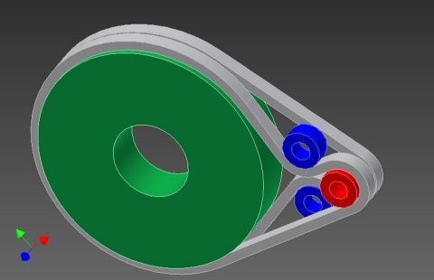
I'm sure it has been done before, but if the two blue pulleys were preloaded toward each other, and allowed to float, then there should be zero backlash, and decent stiffness as you have one straight tensioned leg on each belt. For more reduction, two stages could be used. The pulleys are just extra wide, standard pulleys.
The trick would be coming up with a floating tensioner that would stay in place. I suppose that three belts could be used, the center one twice as wide as the outer two, canceling out the torque caused by the offset between the belts.
Keith"I think this is a very good idea, because in my understanding, the most backlash occurs from the lower tension of one side when changing direction. So if tension is from both sides, this should solve the problem. I've not tested it however. Maybe you want to test it.
-
That's an interesting idea. I bet I could implement something like that. It's like a rotational dampener to help eat up any wobble from spring in the system. I'm working off of 200mm continuous belts for now as those are the most economical in 10 packs from amazon. I'd be happy to source some different sizes if needed though!
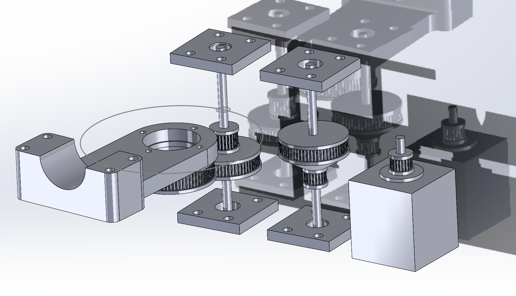
Here's a snapshot of the belt box I'm working on right now. It's just a series of 3:1 belt reducers to the output. With an overall ratio of 27:1 there's no way I'll need a nema 23 anymore, so I'm swapping those out for nema 17's and I'll reuse the 23's for the z axis which is going to need some power to lift this whole system! It's using 5x100mm shaft for the idlers, and some printed bearing blocks fixed between the 80/20 frame.
This is what I was talking about with dual pulleys. I couldn't find much info on the strength of 1x 6mm wide belt. it seems like 6mm gt2 belt is paired with nema 17's but folks tend to go up to 9mm wide belt with nema 23's. We'll see what where we end up, but it wouldn't be hard to add an additional set of belts either to just the arm or the output arm and the stage before that to add some additional stiffness.
-
@michaelr123 it will be interesting to see the results of your tests. Please consider to use 0.9 instead of 1.8 degree steppers (400 instead of 200 steps per rotation). They also have +5 % tolerance for a full step, but that's better precision for the fewer rotation degrees of one step.
I've used a two-stage belt gear with 1:3 and 1:10 instead of three stage 1:3, 1:3, 1:3. The 1:10 can then be an open belt, steel based. (I didn't find closed belt steel belts. Those are the white ones). One topic is how to get good tension (changing the distance of the pulleys, or changing the attachments of the belts).
-
Hello!
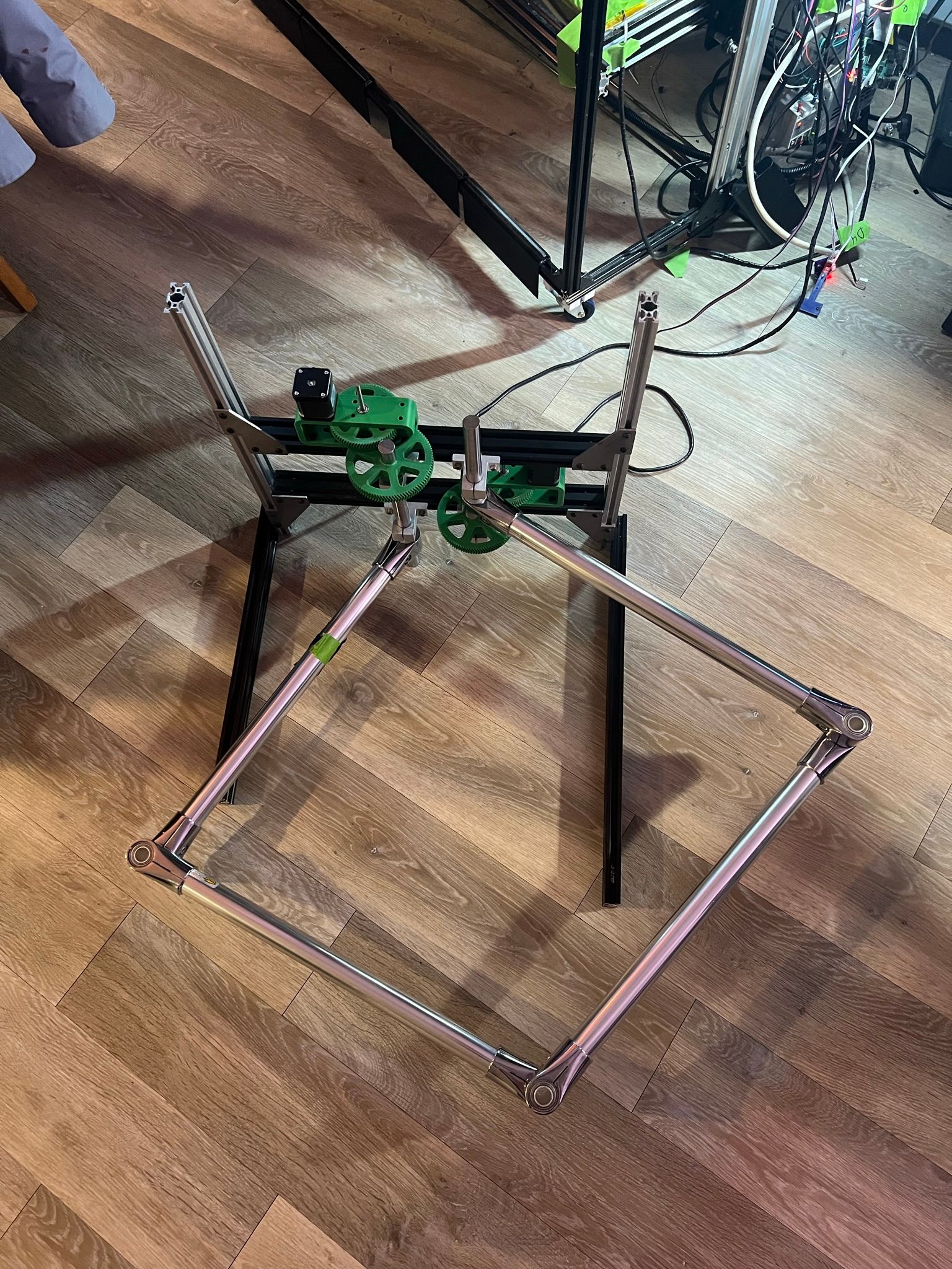
After a bit of a hiatus, I've got something to show off again! I tried my belt-box idea, and that was terrible. There was a ton of backlash as the belts wound up with tension. Instead I decided to make a new gear box with a finer toothed gear (module 1 rather than 2) and a 30:1 ratio to get a ton of precision and torque. I also switched to nema 17 motors which is working great! So now I can move the nema 23's to the Z axis.
I need to get some pillow blocks in for the 20mm rod, but this worked really well just spinning in the static rod mounts I had. I was having a hard time connecting to the tube clamps, so instead I found some 20mm shaft collars that were 32mm for their OD's. This created a static point to mount to the 20mm solid rod which is much easier to mount a gear to.
One thing I could use help with is some sort of rotational dampener. I've got my acceleration and jerk settings down pretty low for 100-150mm/s print moves which is ok (accelerations to 250mm/s^2 and jerk to 2mm/s^3). I'm hoping the pillow blocks I'm getting will just be a bit sticky to introduce some friction to reduce wobble around corners. Ultimately this will be running 1mm nozzles and up, so I don't expect super fast print speeds anyway, but the stiffer I can make the system the better print quality I'll get out of it.
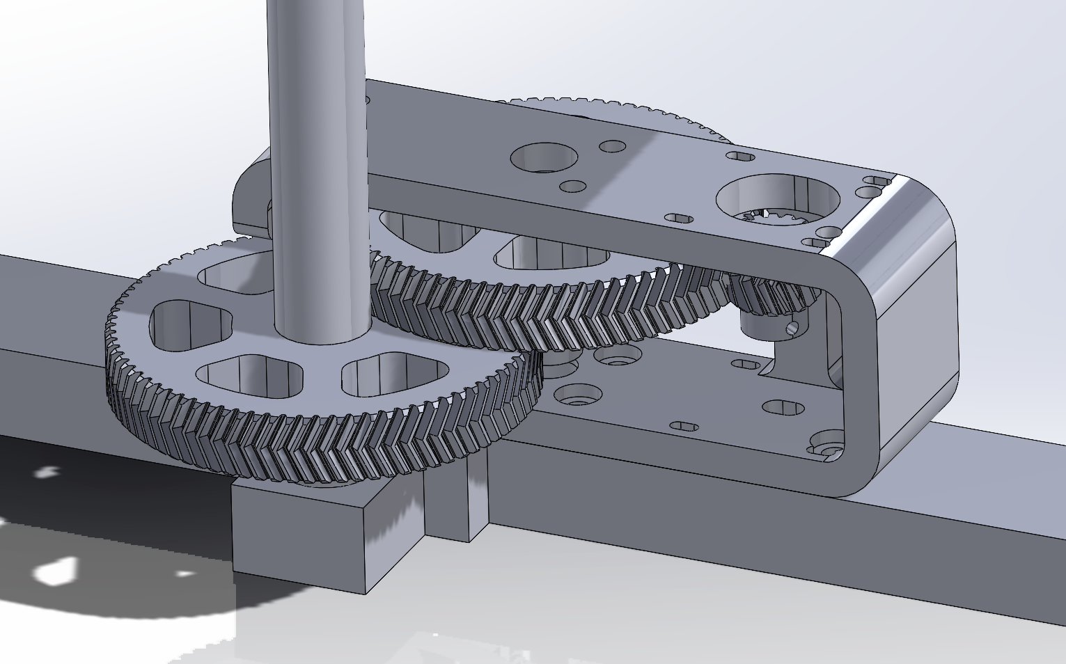
Possible upgrades are to come up with a stiffer design for the gear box housing as I can see it flexes a bit as the gears load up. I'll probably move the idler compound gear to an 8mm shaft rather than a 5mm shaft at some point too.
From here, I think I'm ready to start getting the 80/20 framing sorted so it can be mounted to the Z axis which I need to start putting together and sorting out as well!
-
@michaelr123 said in 5 bar scara on duet3!:
come up with a stiffer design for the gear box housing
nice to hear that you make progress.
For stiffness, bending depends on e-module of materials, which is about 1 to 3 GPa for plastics, 70 for aluminium and steel 210. So connecting two points of the axes with an aluminium construction would be better than plastic housing.
You could use your two horizontal aluminium extrusions and assemble the two steppers upside and the other one downside, so the two big wheels are not in eachs way and use the aluminium extrusion to hold the axes in place.
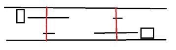
The red lines are the axes connected to the extrusions. M569's direction must be reversed than by changing the S parameter.
To connect aluminiun - holder - ball bearing - shaft I used a SHF16 or other depending on the shaft diameter. SHF is similar like your SH holders, but other orientation (or fixed shaft and wheel on ball bearing, the wheels connected). Anyway, the shaft should be fixed in place at two points. Tilting the shafts or hindering it will be critical for all XYZ positions, because the arms leverage small tiltings. The longer the arms, the more. (I use flanged ball bearings like F688 to hinder it so slip through).
When the axes are stable and the hinges don't have play, I think you'll not need a dampered rotating axis anymore. You could additionally lower acceleration values to have lower vibrations, if acceleration is the cause.
-
@michaelr123 if you ask me for another recommendation (
) , e.g. optimal gear ratio for the wheels, I would say calculate the extrusion rate you can get with the 1mm nozzle and calculate back how the maximum speed of the arms can be. Then choose as much high ratio as possible, maybe 1:50 or even 1:100, because you'll get higher precision.