DELTA FLSUN SR - 6HC - Z Probe Set Up Issues
-
Hello fellow members,
I would be very grateful for any advice on the correct config to set up the manually removable Z probe on the FLSUN SR as I have spent several days now going around in circles. Hardware is 6HC with the latest firmware on both SBC Pi and main board with Duet Web Control 3.4.5 Functionally the z-probe switch is working fine, my problem is finding the correct settings in the config.g. I added M291 pause confirmations for adding and removing the switch to the bed.g file when doing bed calibrations.


I can not get the Z offset and Bed calibration to work, the only way I got Z=0 was by increasing the printer height from 330 to 349, and then when trying a G32 bed calibration, the probe crashed into the bed.
I have tried many Z trigger height offsets with no luck, even removing the config-override.g file and still stuck so I am attaching my config/home and bed files for review and hopefully someone can point me in the right direction.
Any advice would be greatly appreciated
Cheer Ken
-
@KCMARINE This is your current Z probe configuration from config.g:
; Z-Probe M558 P5 C"!io4.in" H5 F120 T6000 ; set Z probe type to switch and the dive height + speeds G31 P500 X0 Y0 Z20 ; set Z probe trigger value, offset and trigger height M557 R85 S20 ; define mesh grid These seem reasonable to start with. For probe calibration, see https://docs.duet3d.com/User_manual/Connecting_hardware/Z_probe_testing
Do the static test first, to check the probe is actually working, and reports 0 when not touching, and 1000 when touching. This also covers setting the probe offset in X,Y and Z.When running bed.g for the first couple of times on a delta, you may need to increase the M558 H parameter. If the delta parameters (M665) are not set accurately, the movement of the effector in X and Y may not be flat, so cause a crash. Try setting it to 20 to start with, so the probe is lifted up higher between probe points. After a couple of runs, the delta parameters should be more accurately set, and you can reduce it again.
Ian
-
@KCMARINE said in DELTA FLSUN SR - 6HC - Z Probe Set Up Issues:
I have tried many Z trigger height offsets with no luck
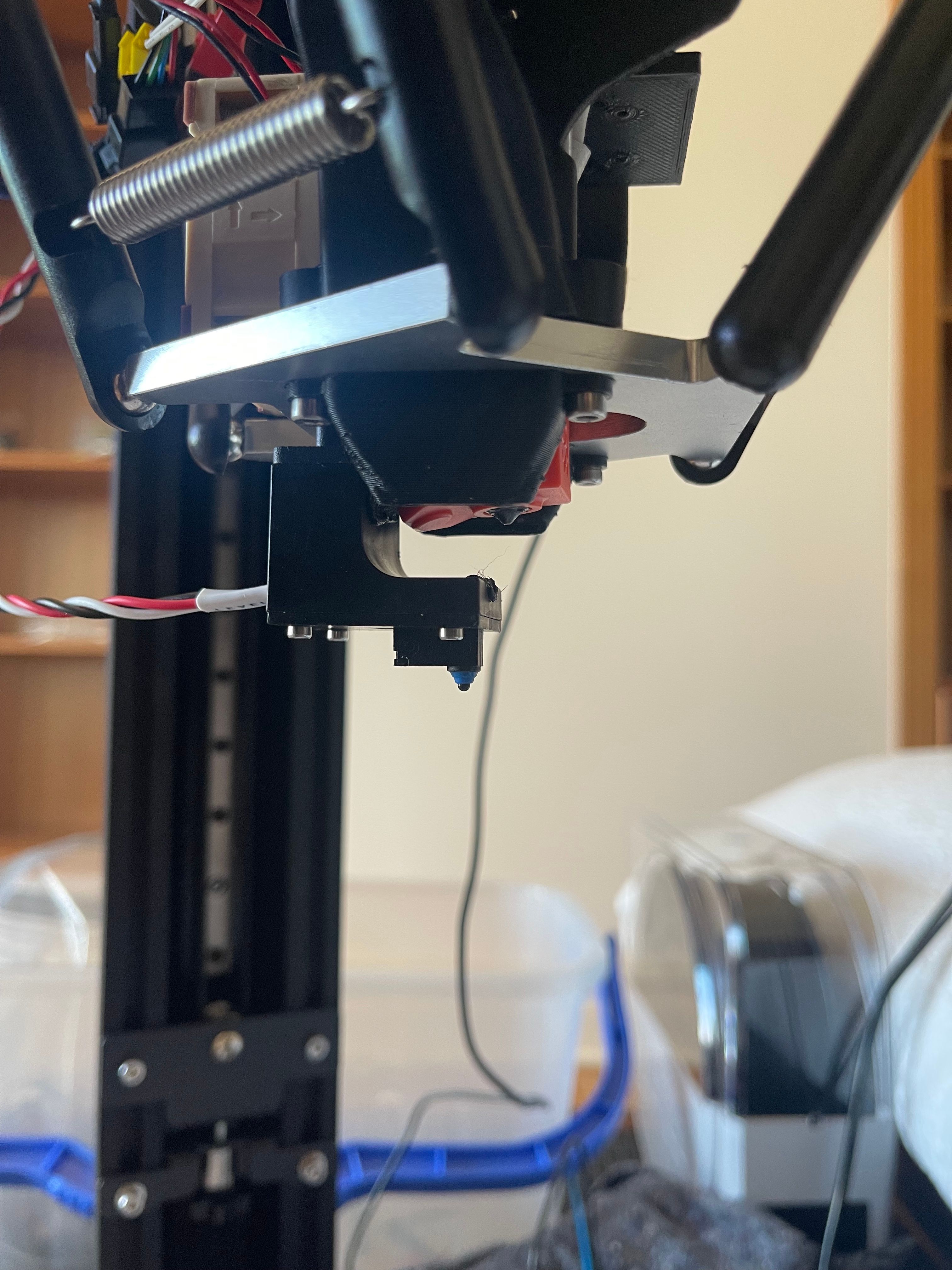
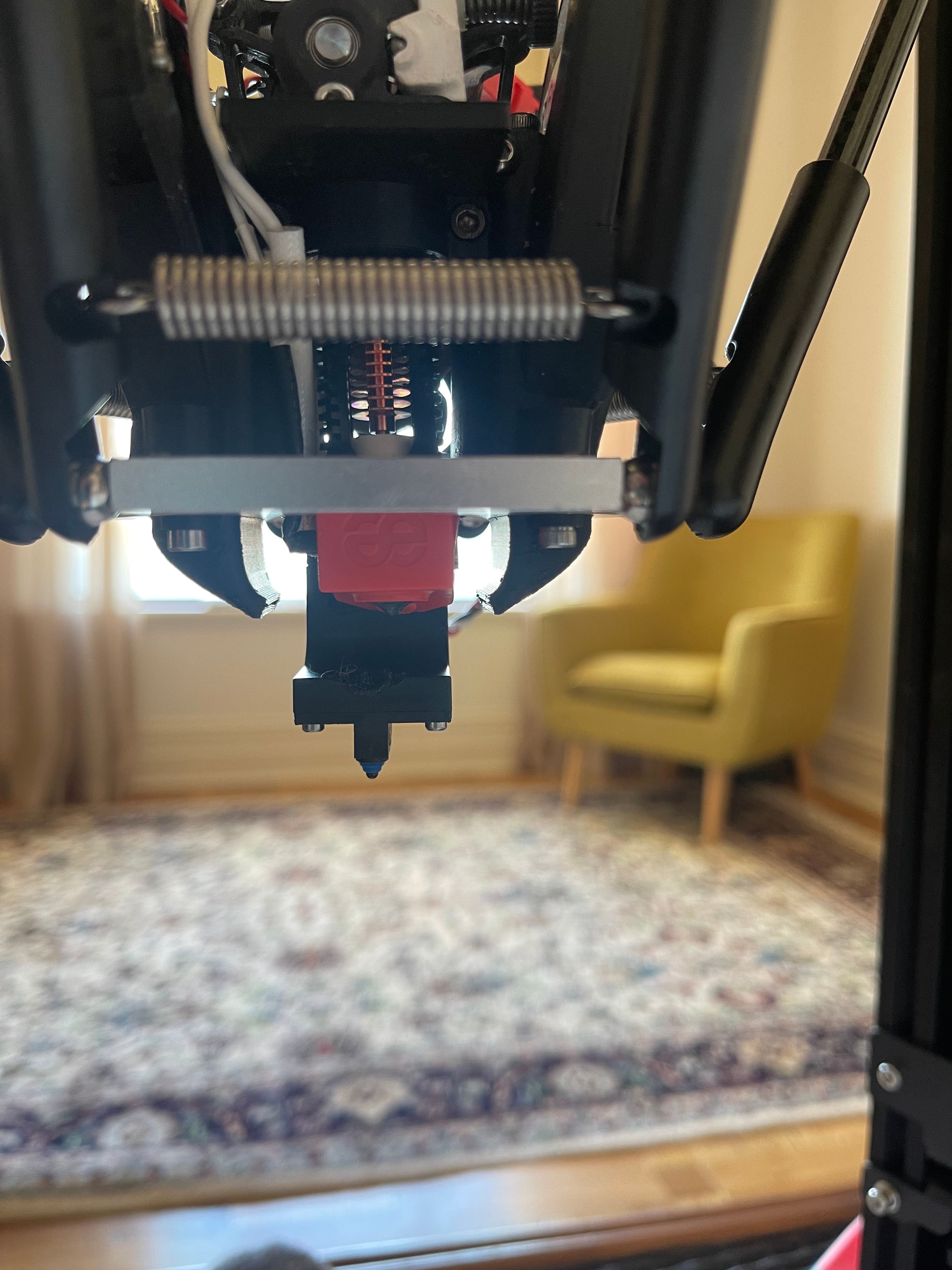
It looks to me that the tip of the switch sits below the tip of the nozzle when the Z probe is fitted. So the G31 Z value will need to be
negativepositive. For example, if the switch tip is 10mm lower than the nozzle tip, use: G31 Z10. -
Thanks for your help @droftarts and @dc42. Greatly appreciated. Unfortunately, I am still at a loss - I have followed the Z_probe_testing docs repeating many times and am still not able to affect Z offset.
I recorded several videos that show that moving either or both H and or Z has no effect on the position of the extruder in the Z direction.
4) Bed Calibration H20 and Z20
Also, the files for
homedelta.g config.g bed.gHoping you can shed some light on this issue as I am at the end of my 3 day investigations.
Many thanks
-
Happy New Year from Australia - my next idea is to roll back to earlier firmware and see if this it changes as it's not possible to change the Z height using the H or Z offsets in G31 on this delta setup?
-
@KCMARINE it’s M558 that has the H parameter. G31 has Z. These work on delta machines; I run a delta machine myself.
Ian
-
Hello @Ian - you are 100% correct, as I have in my config.g file attached and also shown in the videos I have taken. please let me know if you have any difficulty watching them, and you will see that changing either the M558 Hnn or the G31 Znn values does not affect the extruder Z height. Can you tell me what firmware you have installed, please, if this is working for you?
M558 P5 C"!io4.in" H20 F120 T6000 ; set Z probe type to switch and the dive height + speeds G31 P500 X0 Y0 Z20 ; set Z probe trigger value, offset and trigger height M557 R85 S18.45 ; define mesh grid M558 P5 C"!io4.in" H0 F120 T6000 ; set Z probe type to switch and the dive height + speeds G31 P500 X0 Y0 Z0 ; set Z probe trigger value, offset and trigger height M557 R85 S18.45 ; define mesh grid In both examples, the Z effector does not change in Z height as shown in the videos
Would appreciate any assistance
-
@KCMARINE I watched your videos (after fixing the links in your post). At the moment, all that is happening is that you home the X, Y and Z towers, which then sets the Z height to the value set in your delta parameters M665, which I think is currently 330. Then it looks like you are moving down to Z0; you're not probing, it's just a G1 move to Z0, or at least that's what I assume is in the "Move Z to 0" macro. It doesn't look like it's producing an error message that it couldn't reach the bed to probe.
The delta parameter height of 330 is just a starting point, and is currently the only thing that tells the firmware where the bed is once the effector is homed at the top of the towers. This needs to be measured accurately so that Z0 is actually where the nozzle touches the bed, but that can be done and set by probing and delta calibration. It would be best to get it within a few millimetres manually, then it will probe down to the bed the distance set by the M558 H parameter (don't set this to 0, 20 is fine to start with). The M558 H parameter is the dive height; it just sets a limit for how far up and down the probe will move between probing moves. It does not affect anything where probing moves aren't actually done, like in your videos. The same goes for G31 Z parameter. Set this back to 20, you can set this accurately once you actually get it to probe the bed.
My advice is to:
- Get M665 H parameter more accurate. If the nozzle looks like it is 20mm off the bed at Z0, increase the M665 H parameter by 15mm. You're aiming for the nozzle to be closer to the bed that the M558 H parameter (dive height), which should be currently 20mm.
- Test your probe. I can see the probe value is 0 in DWC in your videos. Check that when you press it, it goes to 1000.
- Follow the test and calibrate probe page, to get the correct probe Z offset: https://docs.duet3d.com/User_manual/Connecting_hardware/Z_probe_testing
- Then read the delta calibration page: https://docs.duet3d.com/User_manual/Tuning/Delta_calibration
Ian
-
Many thanks, @droftarts, and to all the admins for the detailed help - greatly appreciate the support. I see now where I was going off track. I was missing the requirement after updating the Znn offset and restarting the main board to then do another bed calibration (G32). The delta is now able to adjust Z to 0 and touch the paper on the build plate. Below is the config.g as a reference for any one else trying to do this upgrade for a FLSUN SR.
; Configuration file for Duet 3 MB 6HC (firmware version 3.3)
; executed by the firmware on start-up
;
; generated by RepRapFirmware Configuration Tool v3.3.15 on Sat Dec 24 2022 13:47:15 GMT+0800 (Australian Western Standard Time); General preferences
M575 P1 S1 B57600 ; enable support for PanelDue
G90 ; send absolute coordinates...
M83 ; ...but relative extruder moves
M550 P"Duet 3" ; set printer name
M665 R151.67 L315 B85 H345 ; Set delta radius, diagonal rod length, printable radius and homed height
M666 X0 Y0 Z0 ; put your endstop adjustments here, or let auto calibration find them; Drives
M569 P0.0 S1 ; physical drive 0.0 goes forwards - X Motor
M569 P0.1 S1 ; physical drive 0.1 goes forwards - Y Motor
M569 P0.2 S1 ; physical drive 0.2 goes forwards - Z Motor
M569 P0.3 S0 ; physical drive 0.3 goes forwards - Extruder Motor
M584 X0.0 Y0.1 Z0.2 E0.3 ; set drive mapping
M350 X16 Y16 Z16 E16 I1 ; configure microstepping with interpolation
M92 X80.00 Y80.00 Z80.00 E338.84 ; set steps per mm
M566 X1200.00 Y1200.00 Z1200.00 E1200.00 ; set maximum instantaneous speed changes (mm/min)
M203 X18000.00 Y18000.00 Z18000.00 E1200.00 ; set maximum speeds (mm/min)
M201 X1000.00 Y1000.00 Z1000.00 E1000.00 ; set accelerations (mm/s^2)
M906 X1000 Y1000 Z1000 E500 I30 ; set motor currents (mA) and motor idle factor in per cent
M84 S30 ; Set idle timeout; Axis Limits
M208 Z0 S1 ; set minimum Z; Endstops
M574 X2 S1 P"io1.in" ; configure switch-type (e.g. microswitch) endstop for high end on X via pin io1.in
M574 Y2 S1 P"io2.in" ; configure switch-type (e.g. microswitch) endstop for high end on Y via pin io2.in
M574 Z2 S1 P"io3.in" ; configure switch-type (e.g. microswitch) endstop for high end on Z via pin io3.in; Z-Probe
M558 P5 C"!io4.in" H10 F120 T6000 ; set Z probe type to switch and the dive height + speeds
G31 P500 X0 Y0 Z25.755 ; set Z probe trigger value, offset and trigger height
M557 R85 S18.45 ; define mesh grid; Heaters
M308 S0 A"HOT-BED" P"temp0" Y"thermistor" T100000 B4138 ; configure sensor 0 as thermistor on pin temp0
M950 H0 C"out0" T0 ; create bed heater output on out0 and map it to sensor 0
M307 H0 R0.531 K0.495:0.000 D3.92 E1.35 S1.00 B0 ; disable bang-bang mode for the bed heater and set PWM limit
M140 H0 ; map heated bed to heater 0
M143 H0 S120 ; set temperature limit for heater 0 to 120C
M308 S1 A"HOT-END" P"temp1" Y"thermistor" T100000 B4138 ; configure sensor 1 as thermistor on pin temp1
M950 H1 C"out1" T1 ; create nozzle heater output on out1 and map it to sensor 1
M307 H1 R3.823 K0.846:0.054 D4.00 E1.35 S1.00 B0 V23.8 ; disable bang-bang mode for heater and set PWM limit
M143 H1 S280 ; set temperature limit for heater 1 to 280C; Fans
; >>Part Cooling Fan
M950 F0 C"out4" Q500 ; create fan 1 on pin out4 and set its frequency
M106 P0 S0 H-1 ; set fan 1 value. Thermostatic control is turned off
; >>Hot End Fan set to start at 45 degrees
M950 F1 C"out7" Q500 ; create fan 0 on pin out4 and set its frequency
M106 P1 S1 H1 T45 ; set fan 0 value. Thermostatic control is turned on; Filament Runout - https://docs.duet3d.com/en/User_manual/Connecting_hardware/Sensors_filament
;M591 D0 P2 C"io5.in" S1 ; simple sensor (high signal when filament present) connected to IO_5 for drive 0.3, enabled
;M591 D0 ; display filament sensor parameters for extruder drive 0; Tools
M563 P0 S"SHERPA" D0 H1 F0 ; define tool 0
G10 P0 X0 Y0 Z0 ; set tool 0 axis offsets
G10 P0 R0 S0 ; set initial tool 0 active and standby temperatures to 0C; Custom settings are not defined
T0 ; select first tool
;M572 D0:1 S0.025 ; Pressure advance for direct drive +++
M501 ; load saved parameters from non-volatile memory
;M911 S10 R11 P"M913 X0 Y0 G91 M83 G1 Z3 E-5 F1000" ; set voltage thresholds and actions to run on power loss -
undefined Phaedrux marked this topic as a question 3 Jan 2023, 20:05
-
undefined Phaedrux has marked this topic as solved 3 Jan 2023, 20:05