Hobbyservo controlled part cooling fan (compressor+valve)
-
I initially copied code for the servo from documentation and the comment is from there. The servo is connected to correct pin on the board. I tested another servo (ms-1.3-9) and it didn't work either. I'm assuming that with servo (MS-1.3-9) brown is negative, Red is positive and orange is PWM. Both servos should be able to handle 5V PWM.
I then switched to using 5V PWM pin "out9" on 6HC and that didnt work either.
The commands I'm sending to test the servo are:
- M280 P1 S0
- M280 P1 S35
Main printer: 3-5 Axis, 400x400x450 Duet 6HC || https://grabcad.com/eetu-4/models
-
@Visionary said in Hobbyservo controlled part cooling fan (compressor+valve):
I initially copied code for the servo from documentation and the comment is from there. The servo is connected to correct pin on the board. I tested another servo (ms-1.3-9) and it didn't work either. I'm assuming that with servo (MS-1.3-9) brown is negative, Red is positive and orange is PWM. Both servos should be able to handle 5V PWM.
Sorry, for avoidance of confusion, can you explicitly set out again what servo wires are connected where on the board and what is in the config.g.
Basically, when you say 'is connected to correct pin on the board' I don't know what that means in the context of someone saying it should be connected to the LASER/VFD pin, but the config.g referring to 'out7' - does that mean you've connected to out7 (which would be correct for the stated config, but wrong electrically, probably) or does it mean you've connected to the LASER pin (which would be correct electrically, but wrong for the stated config).
I also note that according to the posted config.g you've got fan 0 out out9. You can't have both a fan and a servo on that output.
-
Bed-slinger - Mini5+ WiFi/1LC | RRP Fisher v1 - D2 WiFi | Polargraph - D2 WiFi | TronXY X5S - 6HC/Roto | CNC router - 6HC | Tractus3D T1250 - D2 Eth
-
@droftarts said in Hobbyservo controlled part cooling fan (compressor+valve):
@Visionary also, send
M98 P”config.g”And see if reports any errors.
Ian
This gives message : "Warning: Macro file ”config.g” not found"
I switched to attempting to get working the smaller (MS-1.3-9) servo.
I've connected it following way on 6HC:- Orange wire || Out9 (5V PWM)
- Red wire || +5V (external DC-DC converter)
- Brown wire || GND (external DC-DC converter, which is not directly connected atm to main 24V PSU GND)
I've also noticed that at start up the servo moves (after I removed fan assigments), but I still can't move it with G-code commands like M280 P5 S50. Instead the servo makes noise that indicates its trying to hold its position. The servo also makes random twiches and overheats the servo.
Note that I tried to switch number of the (P1) servo to different one (P5).
Current config:
; Configuration file for Duet 3 MB 6HC (firmware version 3.3)
; executed by the firmware on start-up
;
; generated by RepRapFirmware Configuration Tool v3.3.15 on Tue Dec 20 2022 09:34:36 GMT+0200 (Itä-Euroopan normaaliaika)

; General preferences
M575 P1 S1 B57600                            ; enable support for PanelDue
G90                                          ; send absolute coordinates...
M83                                          ; ...but relative extruder moves
M550 P"My Printer"                           ; set printer name
M669 K1                                      ; select CoreXY mode

; Network
M551 P""                                ; set password. This is redacted.
M552 P0.0.0.0 S1                             ; enable network and acquire dynamic address via DHCP
M586 P0 S1                                   ; enable HTTP
M586 P1 S0                                   ; disable FTP
M586 P2 S0                                   ; disable Telnet

; Drives
M569 P0.0 S0                                 ; physical drive 0.0 goes
M569 P0.1 S0                                 ; physical drive 0.1 goes
M569 P0.2 S0                                 	; Z1 motor (Left from user on printer)
M569 P0.3 S1									; Z2 motor (back motor)
M569 P0.4 S0									; Z3 motor (right from user on printer)
M569 P0.5 S1                                 ; physical drive 0.5 goes forwards
M584 X0.1 Y0.0 Z0.2:0.3:0.4 E0.5                     ; set drive mapping
M350 X16 Y16 Z16 E16 I1                      ; configure microstepping with interpolation
M92 X80.00 Y80.00 Z640.00 E420.00            ; set steps per mm
M566 X700.00 Y700.00 Z60.00 E120.00          ; set maximum instantaneous speed changes (mm/min)
M203 X9000.00 Y9000.00 Z600.00 E1800.00      ; set maximum speeds (mm/min)
M201 X1800.00 Y1800.00 Z30.00 E250.00          ; set accelerations (mm/s^2)
M906 X1000 Y1000 Z1200:2600:1200 E800 I30               ; set motor currents (mA) and motor idle factor in per cent
M84 S30                                      ; Set idle timeout

; Axis Limits
M208 X-25.8 Y-10 Z0 S1                             ; set axis minima
M208 X400 Y400 Z490 S0                       ; set axis maxima

; Endstops
M574 X1 S1 P"io1.in"                        ; low end
M574 Y1 S1 P"io2.in"                        ; low end
M574 Z2 S1 P"io3.in+io4.in+io5.in"                        ; Z1, Z2, Z3 High end, Three ball scews


M671 X-80.0:200.0:480.0 Y400.0:-40.0:400.0 ; Z leadscrews are at (-80,400), (200,-40) and (480,400)


; Z-Probe
M558 P0 H5 F120 T6000                        ; disable Z probe but set dive height, probe speed and travel speed
M557 X50:350 Y50:350 S300                     ; define mesh grid

; Heaters
; BED
M308 S0 P"temp1" Y"thermistor" T100000 B3974 ; configure sensor 0 as thermistor on pin temp1
M950 H0 C"out3" T0                           ; create bed heater output on out3 and map it to sensor 0
M307 H0 B1 R0.25 S1.00                             ; enable bang-bang mode for the bed heater and set PWM limit
M140 H0                                      ; map heated bed to heater 0
M143 H0 S120                                 ; set temperature limit for heater 0 to 120C
; HOTEND
M308 S1 P"temp0" Y"pt1000"
;M308 S1 P"temp0" Y"thermistor" T100000 B4725 C7.06e-8 ; configure sensor 1 as thermistor on pin temp0
M950 H1 C"out1" T1                           ; create nozzle heater output on out1 and map it to sensor 1
M307 H1 B0 S1.00                             ; disable bang-bang mode for heater  and set PWM limit
M143 H1 S320                                 ; set temperature limit for heater 1 to 320C

; Fans
;M950 F0 C"out9" Q500                         ; create fan 0 on pin out9 and set its frequency
;M106 P0 S0 H-1                               ; set fan 0 value. Thermostatic control is turned off
;M950 F1 C"out8" Q500                         ; create fan 1 on pin out8 and set its frequency
;M106 P1 S1 H-1                               ; set fan 1 value. Thermostatic control is turned off

; Tools
M563 P0 D0 H1 F0                             ; define tool 0
G10 P0 X0 Y0 Z0                              ; set tool 0 axis offsets
G10 P0 R0 S0                                 ; set initial tool 0 active and standby temperatures to 0C

;Accelerometer
M955 P0 I56 C"spi.cs3+spi.cs2"

; Servo for compressor fan valve
M950 S5 C"out9" 	; assign GPIO port 1 to out9 (Servo header), servo mode
M280 P5 S30			; Move servo with

; Compressor
M950 P2 C"out2" Q0								 ; Compressor ON/OFF SSR
Main printer: 3-5 Axis, 400x400x450 Duet 6HC || https://grabcad.com/eetu-4/models
-
@Visionary try
M98 P”/sys/config.g”Regarding the M280 S parameter, see this note in the Gcode dictionary for M280: https://docs.duet3d.com/en/User_manual/Reference/Gcodes#m280-set-servo-position
Almost all servos accept a pulse width range of at least 1us to 2us, which corresponds to an S parameter range of 44.2 to 141.2 degrees. So for many servos, values in the range 44.2 to 141.2 or alternatively 1000 to 2000 will cover the full operating range of the servo.
It could be your initial S30 is causing problems. Try higher values in the range suggested above.
Ian
Bed-slinger - Mini5+ WiFi/1LC | RRP Fisher v1 - D2 WiFi | Polargraph - D2 WiFi | TronXY X5S - 6HC/Roto | CNC router - 6HC | Tractus3D T1250 - D2 Eth
-
@Visionary said in Hobbyservo controlled part cooling fan (compressor+valve):
I switched to attempting to get working the smaller (MS-1.3-9) servo.
I've connected it following way on 6HC:- Orange wire || Out9 (5V PWM)
- Red wire || +5V (external DC-DC converter)
- Brown wire || GND (external DC-DC converter, which is not directly connected atm to main 24V PSU GND)
I agree with that colour scheme and wiring layout. As previously, I would expect the DC-DC converter to have the 0V in and 0V out connected together internally (if you have a multimeter you could check there's no voltage across them, but I doubt this is the problem).
I've also noticed that at start up the servo moves (after I removed fan assigments), but I still can't move it with G-code commands like M280 P5 S50. Instead the servo makes noise that indicates its trying to hold its position. The servo also makes random twiches and overheats the servo.
That's slightly positive. Twitching servo sounds like it's at least trying to do something.
Current config:
; Servo for compressor fan valve
M950 S5 C"out9" 	; assign GPIO port 1 to out9 (Servo header), servo mode
M280 P5 S30			; Move servo with
Looks OK to me.
I don't see anything wrong. At this point I'm grasping at straws, but:
- try some different S values in M280 (as @droftarts suggests)
- I see the fan is now commented out of the config file, but is anything still physically connected on OUT9? (I don't think it will matter actually, but worth a try disconnecting it if it is?)
- try connecting the orange wire to io7.out and changing the config line to
M950 S1 C"io7.out"andM280 P1 S<whatever>(this is just in case something is up with your out9 on the board, from config it doesn't look like you're using io7 yet)
-
@droftarts said in Hobbyservo controlled part cooling fan (compressor+valve):
@Visionary try
M98 P”/sys/config.g”This didn't work either, got the same error.
Almost all servos accept a pulse width range of at least 1us to 2us, which corresponds to an S parameter range of 44.2 to 141.2 degrees. So for many servos, values in the range 44.2 to 141.2 or alternatively 1000 to 2000 will cover the full operating range of the servo.
I didn't realize to check allowed servo angles. I thought they all started at 0 Degrees.
I checked the correct allowed pulse widths for both servos.
I changed to using microseconds in the command, but that didn't work and I got the same result.Main printer: 3-5 Axis, 400x400x450 Duet 6HC || https://grabcad.com/eetu-4/models
-
@achrn said in Hobbyservo controlled part cooling fan (compressor+valve):
I agree with that colour scheme and wiring layout. As previously, I would expect the DC-DC converter to have the 0V in and 0V out connected together internally (if you have a multimeter you could check there's no voltage across them, but I doubt this is the problem).
Tested the difference in voltage and it was 0V.
- try some different S values in M280 (as @droftarts suggests)
- I see the fan is now commented out of the config file, but is anything still physically connected on OUT9? (I don't think it will matter actually, but worth a try disconnecting it if it is?)
- try connecting the orange wire to io7.out and changing the config line to
M950 S1 C"io7.out"andM280 P1 S<whatever>(this is just in case something is up with your out9 on the board, from config it doesn't look like you're using io7 yet)
Switching S value didn't work (that were on the product page of the servo), but I might keep trying other values anyways. Nothing is connected to out9 (fan) pin. I changed to io7.out in config and rewired the servo and it behaves the same as before.
Btw how do you differentiate between fan pin out9 and 5V PWM pin out9 in config?
The green arrow points to the pin I've been using as out9.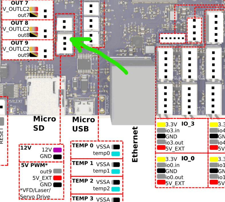
Main printer: 3-5 Axis, 400x400x450 Duet 6HC || https://grabcad.com/eetu-4/models
-
@Visionary said in Hobbyservo controlled part cooling fan (compressor+valve):
Btw how do you differentiate between fan pin out9 and 5V PWM pin out9 in config?
You don't need to. Both pins are driven in parallel - the pin you've arrowed and the OUT9 fan (or whatever) connector next to it are both driven together - the arrowed pin is the control signal (at 5V) and the OUT9 connector next to it is the drain of a MOSFET that has that control signal applied to the gate.
That is, if you have a fan on OUT9 and control that as normal for a fan, the VFD/Laser/Servo pin will also be switching between 0V and 5V but you just leave the pin unconnected and that's not a problem. Alternatively, with the servo connected, the MOSFET is switching on and off in sync, but with nothing on that OUT9 connector that doesn't matter either.
-
@Visionary said in Hobbyservo controlled part cooling fan (compressor+valve):
M98 P”/sys/config.g”
Ugh, sorry, didn't notice on my phone that it was putting in curly quotes rather than straight quotes. Any of these should work to run the config.g and generate any report messages (and possibly errors) from the config:
M98 P"config.g"
M98 P"/sys/config.g"
M98 P"0:/sys/config.g"
For example, I get:
02/01/2023, 19:41:36 	M98 P"config.g"
HTTP is enabled on port 80
FTP is enabled on port 21
TELNET is disabled
02/01/2023, 19:41:54 	M98 P"/sys/config.g"
HTTP is enabled on port 80
FTP is enabled on port 21
TELNET is disabled
02/01/2023, 19:41:59 	M98 P"0:/sys/config.g"
HTTP is enabled on port 80
FTP is enabled on port 21
TELNET is disabled
Ian
Bed-slinger - Mini5+ WiFi/1LC | RRP Fisher v1 - D2 WiFi | Polargraph - D2 WiFi | TronXY X5S - 6HC/Roto | CNC router - 6HC | Tractus3D T1250 - D2 Eth
-
I get:
HTTP is enabled on port 80
FTP is disabled
TELNET is disabled
Is it possible that the servo is broken?
Can incorrect wiring to right pins cause damage to Duet or the servos?
The servos that I have can rotate by hand more than they can by when they are controlled electronically. Do they have to be in certain starting position to work?M122
M122
=== Diagnostics ===
RepRapFirmware for Duet 3 MB6HC version 3.4.5 (2022-11-30 19:35:23) running on Duet 3 MB6HC v1.01 (standalone mode)
Board ID: 08DJM-956BA-NA3TJ-6J9D2-3S06T-9V8GT
Used output buffers: 3 of 40 (14 max)
=== RTOS ===
Static ram: 152760
Dynamic ram: 98776 of which 400 recycled
Never used RAM 98736, free system stack 206 words
Tasks: NETWORK(ready,35.1%,252) ETHERNET(notifyWait,0.2%,561) ACCEL(notifyWait,0.0%,348) HEAT(notifyWait,0.0%,322) Move(notifyWait,0.0%,351) CanReceiv(notifyWait,0.0%,944) CanSender(notifyWait,0.0%,336) CanClock(delaying,0.0%,333) TMC(notifyWait,7.8%,91) MAIN(running,56.6%,925) IDLE(ready,0.2%,30), total 100.0%
Owned mutexes:
=== Platform ===
Last reset 00:00:55 ago, cause: power up
Last software reset at 2023-01-02 16:44, reason: User, GCodes spinning, available RAM 98736, slot 1
Software reset code 0x0003 HFSR 0x00000000 CFSR 0x00000000 ICSR 0x00400000 BFAR 0x00000000 SP 0x00000000 Task MAIN Freestk 0 n/a
Error status: 0x00
Aux0 errors 0,0,0
Step timer max interval 127
MCU temperature: min 28.9, current 39.7, max 39.9
Supply voltage: min 24.3, current 24.4, max 24.4, under voltage events: 0, over voltage events: 0, power good: yes
12V rail voltage: min 12.1, current 12.1, max 12.2, under voltage events: 0
Heap OK, handles allocated/used 0/0, heap memory allocated/used/recyclable 0/0/0, gc cycles 0
Events: 0 queued, 0 completed
Driver 0: standstill, SG min 0, mspos 8, reads 46633, writes 14 timeouts 0
Driver 1: standstill, SG min 0, mspos 8, reads 46633, writes 14 timeouts 0
Driver 2: standstill, SG min 0, mspos 8, reads 46634, writes 14 timeouts 0
Driver 3: standstill, SG min 0, mspos 8, reads 46634, writes 14 timeouts 0
Driver 4: standstill, SG min 0, mspos 8, reads 46634, writes 14 timeouts 0
Driver 5: standstill, SG min 0, mspos 8, reads 46634, writes 14 timeouts 0
Date/time: 2023-01-03 11:35:39
Slowest loop: 4.43ms; fastest: 0.05ms
=== Storage ===
Free file entries: 10
SD card 0 detected, interface speed: 25.0MBytes/sec
SD card longest read time 2.4ms, write time 0.0ms, max retries 0
=== Move ===
DMs created 125, segments created 0, maxWait 0ms, bed compensation in use: none, comp offset 0.000
=== MainDDARing ===
Scheduled moves 0, completed 0, hiccups 0, stepErrors 0, LaErrors 0, Underruns [0, 0, 0], CDDA state -1
=== AuxDDARing ===
Scheduled moves 0, completed 0, hiccups 0, stepErrors 0, LaErrors 0, Underruns [0, 0, 0], CDDA state -1
=== Heat ===
Bed heaters 0 -1 -1 -1 -1 -1 -1 -1 -1 -1 -1 -1, chamber heaters -1 -1 -1 -1, ordering errs 0
=== GCodes ===
Segments left: 0
Movement lock held by null
HTTP is idle in state(s) 0
Telnet is idle in state(s) 0
File is idle in state(s) 0
USB is idle in state(s) 0
Aux is idle in state(s) 0
Trigger is idle in state(s) 0
Queue is idle in state(s) 0
LCD is idle in state(s) 0
SBC is idle in state(s) 0
Daemon is idle in state(s) 0
Aux2 is idle in state(s) 0
Autopause is idle in state(s) 0
Code queue is empty
=== CAN ===
Messages queued 500, received 0, lost 0, boc 0
Longest wait 0ms for reply type 0, peak Tx sync delay 0, free buffers 50 (min 50), ts 279/0/0
Tx timeouts 0,0,278,0,0,220 last cancelled message type 30 dest 127
=== Network ===
Slowest loop: 4.33ms; fastest: 0.03ms
Responder states: HTTP(0) HTTP(0) HTTP(0) HTTP(0) HTTP(0) HTTP(0) FTP(0) Telnet(0) Telnet(0)
HTTP sessions: 1 of 8
= Ethernet =
State: active
Error counts: 0 0 0 1 0 0
Socket states: 5 2 2 2 2 0 0 0
=== Multicast handler ===
Responder is inactive, messages received 0, responses 0