Duet Mini 5 BTT MAX31865 Issue
-
@jay_s_uk
The default switches as I recd it was
Off, Off, Off, On
which was odd as the sensor they supply with the board is a two-wire sensor.
I changed it
On, On, On, Off
Doing so shorts RT+ to Force+ and RT- to Force-The sensor is wired directly to RT+ to one leg of the sensor and RT- to the other leg.
Re the M308 R430, Thanks for the tip

-
@wayneosdias how long are the wires between the Duet daughterboard connector and the MAX31865 board?
-
@dc42 For bench testing just using breadboard jumpers, ~5"
-
@wayneosdias I also just checked that GND Pins 9 and 15 of the MAX pcb are common to each other. Im only using one for GND to the Mini.
-
@wayneosdias I can't see anything wrong with your description of how you have wired it; and 5" of wire should not be a problem.
What message if any do you get when you send the M308 command?
-
@dc42

So thats interesting, does this point to a config problem? havnt changed anything in the config which still is; (sans network settings); Configuration file for Duet 3 Mini 5+ ; executed by the firmware on start-up ; General preferences G90 ; send absolute coordinates... M83 ; ...but relative extruder moves M550 P"Ender 3 Pro" ; set printer name ;M918 P1 E4 F2000000 ; configure direct-connect display ;M918 P2 E4 F2000000 ; configure direct-connect display ;M150 X2 R255 U255 B255 S3 ; set all 3 LEDs to white M575 P1 S2 B57600 ; Network ; Drives M569 P0 S1 D3 V40 ;X0 M569 P1 S1 D3 V40 ;Y0 M569 P2 S0 D3 V40 ;Z0 M569 P3 S0 D3 V40 ;Z1 M569 P4 S1 D3 V40 ;E0 M584 X0 Y1 Z2:3 E4 ;set drive mapping M350 X16 Y16 Z16 E16 I1 ; configure microstepping with interpolation M92 X80.00 Y80.00 Z400.00 E424.90 ; set steps per mm M566 X1200.00 Y1200.00 Z400.00 E300.00 ; set maximum instantaneous speed changes (mm/min) M203 X9000.00 Y9000.00 Z200.00 E6000.00 ; set maximum speeds (mm/min) M201 X500.00 Y500.00 Z100.00 E5000.00 ; set accelerations (mm/s^2) M906 X800 Y800 Z800 E1000 I50 ; set motor currents (mA) and motor idle factor in per cent M84 S30 ; Set idle timeout ; Axis Limits M208 X0 Y0 Z0 S1 ; set axis minima M208 X235 Y235 Z215 S0 ; set axis maxima ; Endstops M574 X1 S1 P"io6.in" ; configure switch-type (e.g. microswitch) endstop for low end on X via pin io5.in M574 Y1 S1 P"io5.in" ; configure switch-type (e.g. microswitch) endstop for low end on Y via pin io6.in ;M574 Z1 S1 P"io2.in" ; configure switch-type (e.g. microswitch) endstop for low end on Z via pin io2.in ; Z-Probe M950 S0 C"io3.out" ; create servo pin 0 for BLTouch M558 P9 C"io3.in" H5 F120 T6000 ; set Z probe type to bltouch and the dive height + speeds G31 P1000 X-32 Y-41 Z1 ; set Z probe trigger value, offset and trigger height M557 X30:190 Y30:190 S20 ; define mesh grid ; Heaters M308 S0 P"temp0" Y"thermistor" T100000 B4092 A"Bed"; configure sensor 0 as thermistor on pin temp0 M950 H0 C"out6" T0 ; create bed heater output on out0 and map it to sensor 0 ;M307 H0 B1 S1.00 ; enable bang-bang mode for the bed heater and set PWM limit ;M307 H0 R1.012 K0.345:0.000 D4.32 E1.35 S1.00 B0 M307 H0 R1.071 K0.348:0.000 D3.57 E1.35 S1.00 B0 M140 H0 ; map heated bed to heater 0 M143 H0 S150 ; set temperature limit for heater 0 to 150C ;Old for thermister ;M308 S1 P"temp1" Y"thermistor" T10000 B4092 ; configure sensor 1 as thermistor on pin temp1 ;M950 H1 C"out1" T1 ; create nozzle heater output on out1 and map it to sensor 1 ;New for PT100 M308 S1 P"spi.cs1" Y"rtd-max31865" M950 H1 C"out1" T1 ; create heater 1 and map sensor 1 ;M307 H1 B0 S1.00 ; disable bang-bang mode for heater and set PWM limit ;M307 H1 R3.416 K0.428:0.000 D10.54 E1.35 S1.00 B0 V23.9 ;M307 H1 R3.288 K0.436:0.000 D11.30 E1.35 S1.00 B0 V23.9 ;M307 H1 R3.209 K0.313:0.000 D11.51 E1.35 S1.00 B0 V23.9 M307 H1 R2.907 K0.303:0.000 D12.84 E1.35 S1.00 B0 V23.9 M143 H1 S275 ; set temperature limit for heater 1 to 275C ; Fans M950 F0 C"out3" Q1000 ; create fan 0 on pin out3 and set its frequency M106 P0 C"PartCool" S0 H-1 ; set fan 0 name and value. Thermostatic control is turned off ;M950 F1 C"out4" Q1000 ; create fan 1 on pin out4 and set its frequency ;M106 P1 C"HotEnd" S1 H1 T45 ; set fan 1 name and value. Thermostatic control is turned on M950 F2 C"out5" Q500 ; create fan 2 on pin out5 and set its frequency M106 P2 C"CaseFan" S1 H1:0 T30 ; set fan 2 name and value. Thermostatic control is turned on M106 P2 C"CaseFan" S1 H1:0 T45 M950 F3 C"out6" Q500 ; create fan 3 on pin out6 and set its frequency M106 P3 C"LEDs" S1 H-1 ; set fan 3 name and value. Thermostatic control is turned off ; Tools M563 P0 D0 H1 F0 G10 P0 X0 Y0 Z0 ; set tool 0 axis offsets G10 P0 R0 S0 ; set initial tool 0 active and standby temperatures to 0C T0 ; select first tool ; Miscellaneous -
@wayneosdias Try running the M308 command for S1 in the console and see if you get any sort of error reported.
-
@gloomyandy
Same as above

-
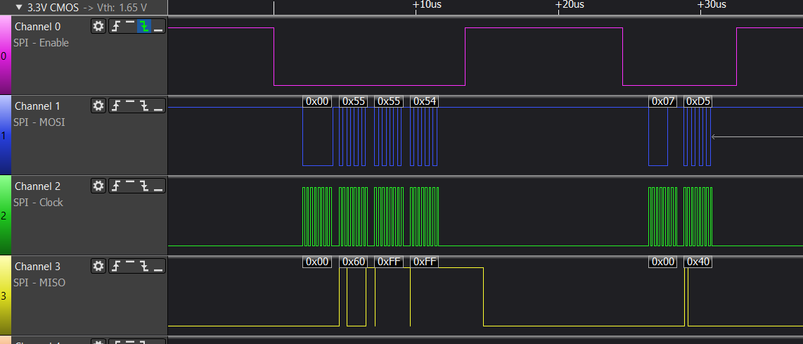
Is there a simple way to test spi on a Duet board? Before pulling out my scope I just put a cheap logic analyzer on CS1 CS2 CLK MOSI and MISO ref'd to ground and no activity. The CS1 CS2 MOSI are logic high as you would expect, and I see no activity either triggered or free running.
Is there anyway to force spi comms to verify HW working?
-
@wayneosdias I meant for you to sent the command:
M308 S1 P"spi.cs1" Y"rtd-max31865"
or using spi.cs2 if that is how it is connected at present.
-
@dc42
Ok got comms sorted. I got this initially

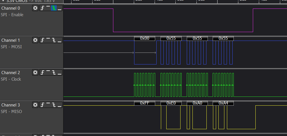
Looks like the MISO line isnt pulled up locally on the the BTT board. I guess this makes sense as the board is meant to plug into 'step stick port' on a BTT driver board. In all the literature I read from BTT/Biqu makes no mention of pullups or active line jumpering. Any way pulled the MISO line up to 3V via 10k and now I get the following;

DWC is also reporting semi resonable values so now just some tuning and firmer wiring to get the ball rolling. I have a Duet PT100 dtr board coming from filastruda and I dont think ill have it for a week. I also ordered an Adafruit MAX31865 bob that should be here tomorrow so Ill follow up this thread on how that gos.Huge thanks for this Forum and support, the best

-
 undefined wayneosdias marked this topic as a question
-
 undefined wayneosdias has marked this topic as solved