Duet Mini 5 BTT MAX31865 Issue
-
I had a baseline configuration for an Ender 3 with the mini 5 and all systems working.
I since updated to an Biqu H2 extruder that uses a PT100. I have a Duet PT100 Dtr board on order, but in the meantime... The H2 shipped with a MAX31865 'stick' and I trying to get it to work w no success. Following the pinouts for the MAX I connected to the Mini 5 via 'TEMP DAUGHTERBOARD' Header and Jumper'd/set switches for 2 wire. The MAX31865 lights up but I receive
"Event notification
Heater 1 fault: failed to read sensor: unknown sensor"
Ive tried swapping MO/SO lines with no success.In config ive tried;
M308 S1 P"spi.cs1" Y"rtd-max31865"
M308 S1 P"spi.cs2" Y"rtd-max31865"No worky

Some addl info
GeneralBoard: Duet 3 Mini 5+ (Mini5plus) Firmware: RepRapFirmware for Duet 3 Mini 5+ 3.4.5 (2022-11-30) Duet WiFi Server Version: 1.27config.g
; Configuration file for Duet 3 Mini 5+
; executed by the firmware on start-up
; General preferences
G90                                          ; send absolute coordinates...
M83                                          ; ...but relative extruder moves

M575 P1 S2 B57600
; Network

; Drives
M569 P0 S1 D3 V40							;X0
M569 P1 S1 D3 V40                           ;Y0
M569 P2 S0 D3 V40                           ;Z0
M569 P3 S0 D3 V40                           ;Z1
M569 P4 S1 D3 V40                           ;E0
M584 X0 Y1 Z2:3 E4                     		;set drive mapping


M350 X16 Y16 Z16 E16 I1                      ; configure microstepping with interpolation
M92 X80.00 Y80.00 Z400.00 E424.90             ; set steps per mm
M566 X1200.00 Y1200.00 Z400.00 E300.00        ; set maximum instantaneous speed changes (mm/min)
M203 X9000.00 Y9000.00 Z200.00 E6000.00      ; set maximum speeds (mm/min)
M201 X500.00 Y500.00 Z100.00 E5000.00        ; set accelerations (mm/s^2)
M906 X800 Y800 Z800 E1000 I50                ; set motor currents (mA) and motor idle factor in per cent
M84 S30                                      ; Set idle timeout

; Axis Limits
M208 X0 Y0 Z0 S1                             ; set axis minima
M208 X235 Y235 Z215 S0                       ; set axis maxima

; Endstops
M574 X1 S1 P"io6.in"                         ; configure switch-type (e.g. microswitch) endstop for low end on X via pin io5.in
M574 Y1 S1 P"io5.in"                         ; configure switch-type (e.g. microswitch) endstop for low end on Y via pin io6.in
;M574 Z1 S1 P"io2.in"                         ; configure switch-type (e.g. microswitch) endstop for low end on Z via pin io2.in

; Z-Probe
M950 S0 C"io3.out"                           ; create servo pin 0 for BLTouch
M558 P9 C"io3.in" H5 F120 T6000              ; set Z probe type to bltouch and the dive height + speeds
G31 P1000 X-32 Y-41 Z1                      ; set Z probe trigger value, offset and trigger height
M557 X30:190 Y30:190 S20                       ; define mesh grid

; Heaters
M308 S0 P"temp0" Y"thermistor" T100000 B4092 A"Bed"; configure sensor 0 as thermistor on pin temp0
M950 H0 C"out6" T0                           ; create bed heater output on out0 and map it to sensor 0
;M307 H0 B1 S1.00                             ; enable bang-bang mode for the bed heater and set PWM limit
;M307 H0 R1.012 K0.345:0.000 D4.32 E1.35 S1.00 B0
M307 H0 R1.071 K0.348:0.000 D3.57 E1.35 S1.00 B0
M140 H0                                      ; map heated bed to heater 0
M143 H0 S150     ; set temperature limit for heater 0 to 150C
;Old for thermister
;M308 S1 P"temp1" Y"thermistor" T10000 B4092 ; configure sensor 1 as thermistor on pin temp1
;M950 H1 C"out1" T1                           ; create nozzle heater output on out1 and map it to sensor 1
;New for PT100
M308 S1 P"spi.cs1" Y"rtd-max31865"
M950 H1 C"out1" T1 ; create heater 1 and map sensor 1

;M307 H1 B0 S1.00                             ; disable bang-bang mode for heater  and set PWM limit
;M307 H1 R3.416 K0.428:0.000 D10.54 E1.35 S1.00 B0 V23.9
;M307 H1 R3.288 K0.436:0.000 D11.30 E1.35 S1.00 B0 V23.9
;M307 H1 R3.209 K0.313:0.000 D11.51 E1.35 S1.00 B0 V23.9
M307 H1 R2.907 K0.303:0.000 D12.84 E1.35 S1.00 B0 V23.9
M143 H1 S275                                 ; set temperature limit for heater 1 to 275C

; Fans
M950 F0 C"out3" Q1000                         ; create fan 0 on pin out3 and set its frequency
M106 P0 C"PartCool" S0 H-1                   ; set fan 0 name and value. Thermostatic control is turned off
;M950 F1 C"out4" Q1000                         ; create fan 1 on pin out4 and set its frequency
;M106 P1 C"HotEnd" S1 H1 T45                  ; set fan 1 name and value. Thermostatic control is turned on
M950 F2 C"out5" Q500                         ; create fan 2 on pin out5 and set its frequency
M106 P2 C"CaseFan" S1 H1:0 T30                ; set fan 2 name and value. Thermostatic control is turned on M106 P2 C"CaseFan" S1 H1:0 T45
M950 F3 C"out6" Q500                         ; create fan 3 on pin out6 and set its frequency
M106 P3 C"LEDs" S1 H-1                       ; set fan 3 name and value. Thermostatic control is turned off

; Tools
M563 P0 D0 H1 F0
G10 P0 X0 Y0 Z0                              ; set tool 0 axis offsets
G10 P0 R0 S0                                 ; set initial tool 0 active and standby temperatures to 0C
T0         ; select first tool
; Miscellaneous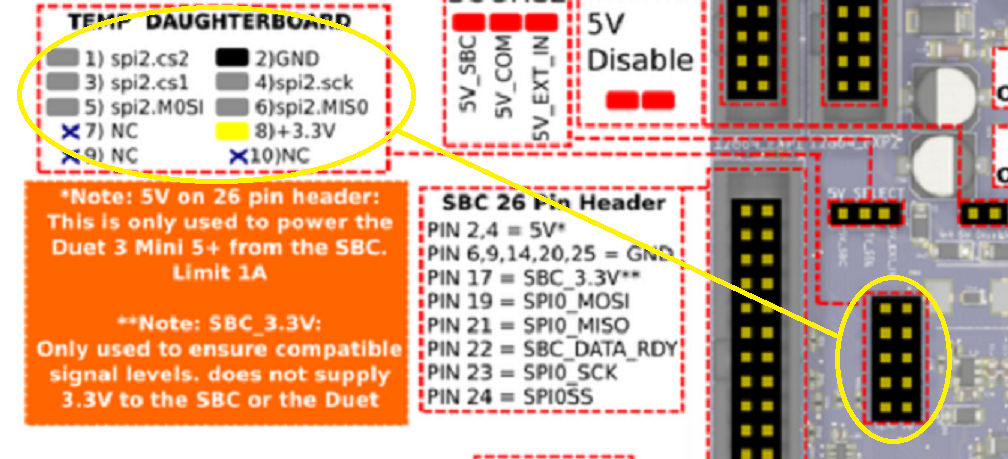
Anything stick out to anyone?
-
@wayneosdias can you be a bit more explicit about what pins you've connected together?
-
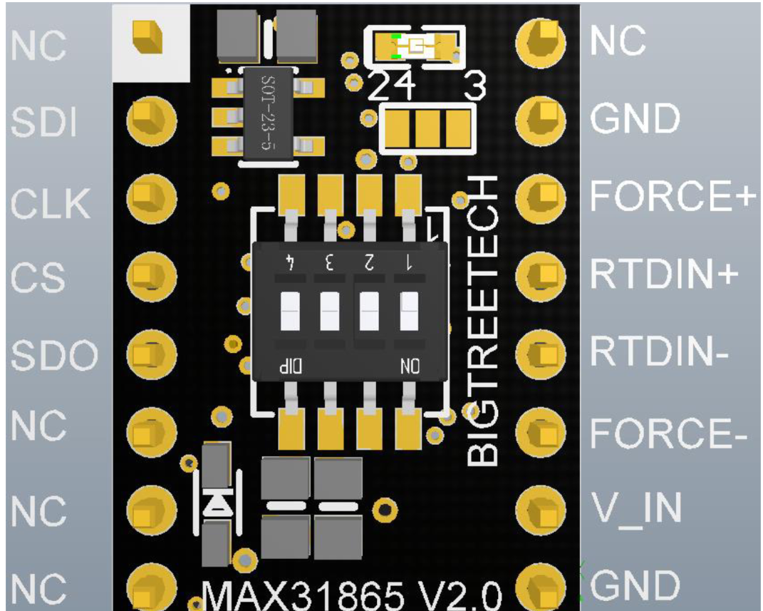
@jay_s_uk Sure, referencing the MAX31865 pcb numbered a classic dip and the Duet 'TEMP DAUGHTER' header as a header the connections are;
MAX / Duet
1 NC / -
2 SDI / 5 MOSI
3 CLK / 4 SCK
4 CS / 1 CS2 or 3CS1
5 SDO / 6 MISO
6 NC / -
7 NC / -
8 NC / -
9 GND / 2 GND
10 V_IN / 8 +3.3V
11 FORCE- common to 12 RTDIN- / -
13 RTDIN+ common to 14 FORCE+ / -
15 GND / -
16 NC / - -
@wayneosdias how do you have the dip switches set?
where are you connecting the PT100 to?
FYI, you'll also have to addR430to the M308 line as it uses a different sense resistor than the one expected by the firmware by default -
@jay_s_uk
The default switches as I recd it was
Off, Off, Off, On
which was odd as the sensor they supply with the board is a two-wire sensor.
I changed it
On, On, On, Off
Doing so shorts RT+ to Force+ and RT- to Force-The sensor is wired directly to RT+ to one leg of the sensor and RT- to the other leg.
Re the M308 R430, Thanks for the tip
")
-
@wayneosdias how long are the wires between the Duet daughterboard connector and the MAX31865 board?
Duet WiFi hardware designer and firmware engineer
Please do not ask me for Duet support via PM or email, use the forum
http://www.escher3d.com, https://miscsolutions.wordpress.com -
@dc42 For bench testing just using breadboard jumpers, ~5"
-
@wayneosdias I also just checked that GND Pins 9 and 15 of the MAX pcb are common to each other. Im only using one for GND to the Mini.
-
@wayneosdias I can't see anything wrong with your description of how you have wired it; and 5" of wire should not be a problem.
What message if any do you get when you send the M308 command?
Duet WiFi hardware designer and firmware engineer
Please do not ask me for Duet support via PM or email, use the forum
http://www.escher3d.com, https://miscsolutions.wordpress.com -
@dc42
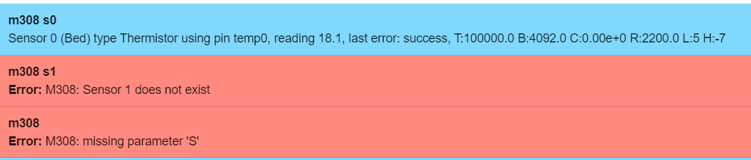
So thats interesting, does this point to a config problem? havnt changed anything in the config which still is; (sans network settings); Configuration file for Duet 3 Mini 5+ ; executed by the firmware on start-up ; General preferences G90 ; send absolute coordinates... M83 ; ...but relative extruder moves M550 P"Ender 3 Pro" ; set printer name ;M918 P1 E4 F2000000 ; configure direct-connect display ;M918 P2 E4 F2000000 ; configure direct-connect display ;M150 X2 R255 U255 B255 S3 ; set all 3 LEDs to white M575 P1 S2 B57600 ; Network ; Drives M569 P0 S1 D3 V40 ;X0 M569 P1 S1 D3 V40 ;Y0 M569 P2 S0 D3 V40 ;Z0 M569 P3 S0 D3 V40 ;Z1 M569 P4 S1 D3 V40 ;E0 M584 X0 Y1 Z2:3 E4 ;set drive mapping M350 X16 Y16 Z16 E16 I1 ; configure microstepping with interpolation M92 X80.00 Y80.00 Z400.00 E424.90 ; set steps per mm M566 X1200.00 Y1200.00 Z400.00 E300.00 ; set maximum instantaneous speed changes (mm/min) M203 X9000.00 Y9000.00 Z200.00 E6000.00 ; set maximum speeds (mm/min) M201 X500.00 Y500.00 Z100.00 E5000.00 ; set accelerations (mm/s^2) M906 X800 Y800 Z800 E1000 I50 ; set motor currents (mA) and motor idle factor in per cent M84 S30 ; Set idle timeout ; Axis Limits M208 X0 Y0 Z0 S1 ; set axis minima M208 X235 Y235 Z215 S0 ; set axis maxima ; Endstops M574 X1 S1 P"io6.in" ; configure switch-type (e.g. microswitch) endstop for low end on X via pin io5.in M574 Y1 S1 P"io5.in" ; configure switch-type (e.g. microswitch) endstop for low end on Y via pin io6.in ;M574 Z1 S1 P"io2.in" ; configure switch-type (e.g. microswitch) endstop for low end on Z via pin io2.in ; Z-Probe M950 S0 C"io3.out" ; create servo pin 0 for BLTouch M558 P9 C"io3.in" H5 F120 T6000 ; set Z probe type to bltouch and the dive height + speeds G31 P1000 X-32 Y-41 Z1 ; set Z probe trigger value, offset and trigger height M557 X30:190 Y30:190 S20 ; define mesh grid ; Heaters M308 S0 P"temp0" Y"thermistor" T100000 B4092 A"Bed"; configure sensor 0 as thermistor on pin temp0 M950 H0 C"out6" T0 ; create bed heater output on out0 and map it to sensor 0 ;M307 H0 B1 S1.00 ; enable bang-bang mode for the bed heater and set PWM limit ;M307 H0 R1.012 K0.345:0.000 D4.32 E1.35 S1.00 B0 M307 H0 R1.071 K0.348:0.000 D3.57 E1.35 S1.00 B0 M140 H0 ; map heated bed to heater 0 M143 H0 S150 ; set temperature limit for heater 0 to 150C ;Old for thermister ;M308 S1 P"temp1" Y"thermistor" T10000 B4092 ; configure sensor 1 as thermistor on pin temp1 ;M950 H1 C"out1" T1 ; create nozzle heater output on out1 and map it to sensor 1 ;New for PT100 M308 S1 P"spi.cs1" Y"rtd-max31865" M950 H1 C"out1" T1 ; create heater 1 and map sensor 1 ;M307 H1 B0 S1.00 ; disable bang-bang mode for heater and set PWM limit ;M307 H1 R3.416 K0.428:0.000 D10.54 E1.35 S1.00 B0 V23.9 ;M307 H1 R3.288 K0.436:0.000 D11.30 E1.35 S1.00 B0 V23.9 ;M307 H1 R3.209 K0.313:0.000 D11.51 E1.35 S1.00 B0 V23.9 M307 H1 R2.907 K0.303:0.000 D12.84 E1.35 S1.00 B0 V23.9 M143 H1 S275 ; set temperature limit for heater 1 to 275C ; Fans M950 F0 C"out3" Q1000 ; create fan 0 on pin out3 and set its frequency M106 P0 C"PartCool" S0 H-1 ; set fan 0 name and value. Thermostatic control is turned off ;M950 F1 C"out4" Q1000 ; create fan 1 on pin out4 and set its frequency ;M106 P1 C"HotEnd" S1 H1 T45 ; set fan 1 name and value. Thermostatic control is turned on M950 F2 C"out5" Q500 ; create fan 2 on pin out5 and set its frequency M106 P2 C"CaseFan" S1 H1:0 T30 ; set fan 2 name and value. Thermostatic control is turned on M106 P2 C"CaseFan" S1 H1:0 T45 M950 F3 C"out6" Q500 ; create fan 3 on pin out6 and set its frequency M106 P3 C"LEDs" S1 H-1 ; set fan 3 name and value. Thermostatic control is turned off ; Tools M563 P0 D0 H1 F0 G10 P0 X0 Y0 Z0 ; set tool 0 axis offsets G10 P0 R0 S0 ; set initial tool 0 active and standby temperatures to 0C T0 ; select first tool ; Miscellaneous -
@wayneosdias Try running the M308 command for S1 in the console and see if you get any sort of error reported.
-
@gloomyandy
Same as above

-
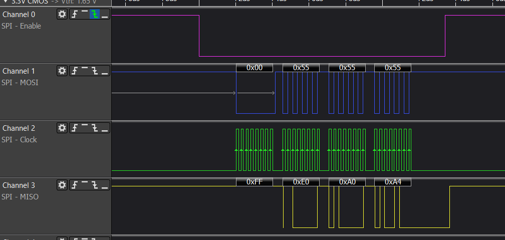
Is there a simple way to test spi on a Duet board? Before pulling out my scope I just put a cheap logic analyzer on CS1 CS2 CLK MOSI and MISO ref'd to ground and no activity. The CS1 CS2 MOSI are logic high as you would expect, and I see no activity either triggered or free running.
Is there anyway to force spi comms to verify HW working?
-
@wayneosdias I meant for you to sent the command:
M308 S1 P"spi.cs1" Y"rtd-max31865"
or using spi.cs2 if that is how it is connected at present.
Duet WiFi hardware designer and firmware engineer
Please do not ask me for Duet support via PM or email, use the forum
http://www.escher3d.com, https://miscsolutions.wordpress.com -
@dc42
Ok got comms sorted. I got this initially
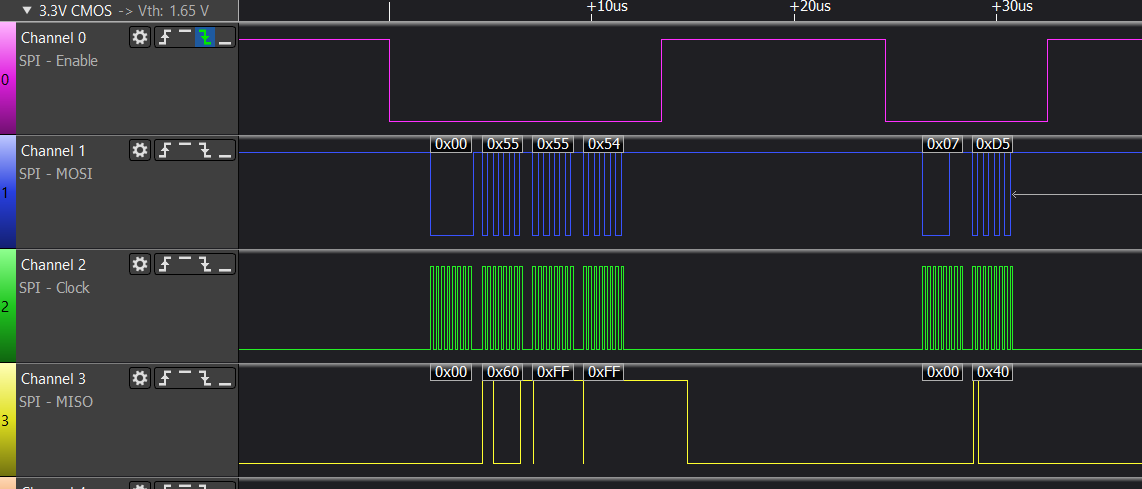
Looks like the MISO line isnt pulled up locally on the the BTT board. I guess this makes sense as the board is meant to plug into 'step stick port' on a BTT driver board. In all the literature I read from BTT/Biqu makes no mention of pullups or active line jumpering. Any way pulled the MISO line up to 3V via 10k and now I get the following;
DWC is also reporting semi resonable values so now just some tuning and firmer wiring to get the ball rolling. I have a Duet PT100 dtr board coming from filastruda and I dont think ill have it for a week. I also ordered an Adafruit MAX31865 bob that should be here tomorrow so Ill follow up this thread on how that gos.Huge thanks for this Forum and support, the best
")
-
 undefined wayneosdias marked this topic as a question
-
undefined wayneosdias has marked this topic as solved