Duet3D Logo Duet3D
    • Tags
    • Documentation
    • Order
    • Register
    • Login

    Expansion Header Ex_STOP pins

    Scheduled Pinned Locked Moved
    Duet Hardware and wiring
    3
    9
    333
    Loading More Posts
    • Oldest to Newest
    • Newest to Oldest
    • Most Votes
    Reply
    • Reply as topic
    Log in to reply
    This topic has been deleted. Only users with topic management privileges can see it.
    • Nordleundefined
      Nordle
      last edited by Nordle

      How am I supposed to wire these up?
      using Duet2wifi

      alankilianundefined 1 Reply Last reply Reply Quote 0
      • alankilianundefined
        alankilian @Nordle
        last edited by alankilian

        @Nordle Those are the endstop inputs for the axis on the expansion connector.

        They perform the function just like X,Y and Z_STOP inputs.

        See THIS PAGE for more information.

        There are differences:

        • No input protection
        • No indicator LED
        • No pullup resistor

        Basically, it's a RAW input to the processor so you'll need to provide additional circuitry for your specific switches.

        SeemeCNC Rostock Max V3 converted to V3.2 with a Duet2 Ethernet Firmware 3.2 and SE300

        Nordleundefined 1 Reply Last reply Reply Quote 2
        • Nordleundefined
          Nordle @alankilian
          last edited by

          @alankilian Thanks.

          What would be the simplest way to wire those up?
          Could I wire a normally closed switch with +3.3V from Expansion Header also?

          alankilianundefined 1 Reply Last reply Reply Quote 0
          • alankilianundefined
            alankilian @Nordle
            last edited by

            @Nordle The most compatible way would be to duplicate the input circuitry used for the X, Y and Z_STOP inputs like this:

            Capture.PNG

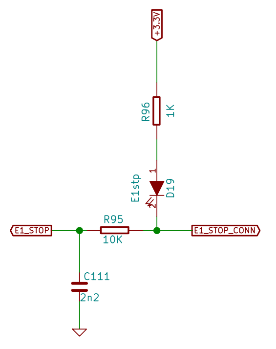
            Then connect your normally-closed switch between ground and Ex_STOP_CONN in this schematic.

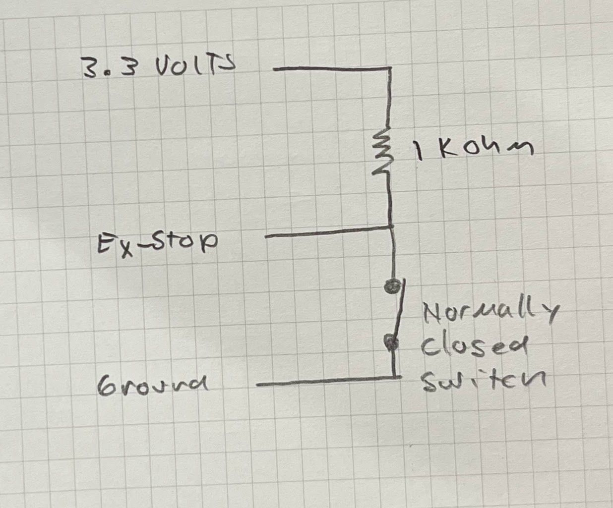
            If you want a more simple input without all the protections and lights, you can try this:
            IMG_8404.jpg

            SeemeCNC Rostock Max V3 converted to V3.2 with a Duet2 Ethernet Firmware 3.2 and SE300

            Nordleundefined 2 Replies Last reply Reply Quote 3
            • Nordleundefined
              Nordle @alankilian
              last edited by

              This post is deleted!
              1 Reply Last reply Reply Quote 0
              • Nordleundefined
                Nordle @alankilian
                last edited by

                @alankilian Thanks again for the detailed answer.

                I have currently wired drives 5 to 9 form the expansion header to a Ramps1.6 board. It would be very convenient for me to also wire the endstops to the same.

                If I take the simple approach without LEDs, I could just solder the required resistor to the underside of the endstop pins of the ramps like this:
                Endstops Ramps.png
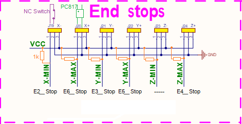
                Am I missing something or could this work?

                Phaedruxundefined alankilianundefined 2 Replies Last reply Reply Quote 0
                • Phaedruxundefined
                  Phaedrux Moderator @Nordle
                  last edited by

                  @Nordle said in Expansion Header Ex_STOP pins:

                  I have currently wired drives 5 to 9 form the expansion header to a Ramps1.6 board

                  What kind of project are you working on?

                  Z-Bot CoreXY Build | Thingiverse Profile

                  Nordleundefined 1 Reply Last reply Reply Quote 0
                  • Nordleundefined
                    Nordle @Phaedrux
                    last edited by Nordle

                    @Phaedrux Currently it is a coreXY with triple Z, might want to add something like automatic toolchange or ERCF(MMU) in the future, so the endstops will be handy. The printer currently runs with some crappy dupont connections and I'm cleaning up some wiring right now

                    1 Reply Last reply Reply Quote 0
                    • Nordleundefined Nordle marked this topic as a question
                    • Nordleundefined Nordle marked this topic as a regular topic
                    • alankilianundefined
                      alankilian @Nordle
                      last edited by

                      @Nordle Yes, you can solder the pullup resistors to the pins on the back of connectors.

                      The electrons don't know where you added the pullups, just that they are there.

                      SeemeCNC Rostock Max V3 converted to V3.2 with a Duet2 Ethernet Firmware 3.2 and SE300

                      1 Reply Last reply Reply Quote 1
                      • First post
                        Last post
                      Unless otherwise noted, all forum content is licensed under CC-BY-SA