Skew calibration with calibration square? Maths help needed
-
@OwenD Thanks for chiming in! I was thinking about this earlier, and I think you are correct. I took the Marlin formulae as correct, and didn't think it through. The shape produced from misaligned axes would be a rhombus not a parallelogram. The two axes, assuming they have been configured correctly, should move the set distance in their plane, so the square would deform into a rhombus.
So, we shouldn't be calculating AB; AB = AD. Your calculations work in the same way as mine, taken from Marlin; AB is calculated where the point B is perpendicular to AD, at the distance AD. I haven't sat down and drawn out the two formula that Marlin uses, I took it that they were correct... but perhaps they are not! I did notice some small differences when calculating the skew factor from the Marlin formulae vs from the measured skew (the old way of doing it).
The interesting thing about the old way of doing this is that it is unambiguous. Take this:
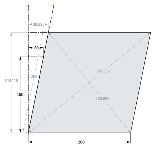
If you measure up 150mm, you get a skew distance of 30mm. Skew factor is 30/150=0.2
If I run these diagonals and AD of 200 through yours I get 0.1999988, and through mine I also get 0.1999988, which is, arguably, very close. But it feels it should work out to 0.2!However, as we're assuming the square deforms into a rhombus, the nice thing is that it makes an isosceles triangle with the diagonal measurements. So the trigonometry should be easy to do. But tomorrow, because it's a bit late here.
Ian
Bed-slinger - Mini5+ WiFi/1LC | RRP Fisher v1 - D2 WiFi | Polargraph - D2 WiFi | TronXY X5S - 6HC/Roto | CNC router - 6HC | Tractus3D T1250 - D2 Eth
-
@droftarts
I just realised I made a mistake in my calculations.
It only affected the calculation of the expected length of the diagonals and the area.
I was using the area of the square and not the rhombus.
If I use these dimensions with the RRF method and with my macro the results are essentially the same..
RRF Method

My macro

-
@droftarts I just meant to use the feature that allows you to give macros an unused gcode name and then calling that, without changes to the firmware (-;
-
@oliof ah, yes, that could work too, once we decide on the correct calculations! I’ve been composing a longer reply for those for the last couple of days!
Ian
-
I spent a bit of time looking at this, and have come to the conclusion that doing it the Marlin way is ... fine. A rhombus is a parallelogram with some extra constraints. If we knew that the shape created by misaligned axes was always going to be a rhombus, only the diagonals would need measuring, and everything else could be worked out from that. Using the Marlin formulae, it covers parallelograms AND rhombuses, though you need to provide the extra AD measurement. Realistically, I'd guess that diagonals can only be measured to an accuracy of perhaps 0.25mm (depending on accuracy of print/bulges/measuring device), so it's never going to be perfect, but certainly good enough.
And just because I wanted to know, I looked up what the two formulae Marlin uses are.
Compute AB : SQRT(2ACAC+2BDBD-4ADAD)/2
This is the parallelogram (and so also works for rhombi) formula to calculate the length of a side from the diagonals and the other side, see https://onlinemschool.com/math/formula/parallelogram/#h3
This can also be written asSQRT((AC*AC+BD*BD-AD*AD)/2)XY_SKEW_FACTOR : TAN(PI/2-ACOS((ACAC-ABAB-ADAD)/(2AB*AD)))
ACOS((AC*AC-AB*AB-AD*AD)/(2*AB*AD))This part is the 'Law of cosines' https://en.wikipedia.org/wiki/Law_of_cosines, and calculates the angle in radians at A given AB, AC and AD. See also https://www.calculatorsoup.com/calculators/geometry-plane/parallelogram.php
TAN(PI/2-A)gives the angle at A, ie between AE (the vertical point above A) and AB, and then using tan gives the skew factor.@OwenD I had a look at your macro, and it works fine for me... in 3.5b1, because of the use of M291 S4 and S6! I also saw that you calculated some of the rhombus values, like area and the second diagonal from the first diagonal and AD, but then these weren't used in the calculations, I think?
@oliof Here's a generalised skew calculator macro. It also calculates the skew in mm, like the physical RRF method would measure, as a sense check. I'll do a M556.1 version when everyone agrees this is the best method, and I have some time!
; skew_calculator.g
;
; Bed Skew Compensation
;
; This feature corrects for misalignment in the XYZ axes.
;
; Take the following steps to get the bed skew in the XY plane:
; 1. Print a test square, e.g. https://www.thingiverse.com/thing:2563185 or https://www.thingiverse.com/thing:2972743
; 2. Mark the test point corners A,B,C,D as per the diagram below, if not already on the print
;
;    Y
;    ^  E--B-------C
;    |  | /       /
;    |  |/       /
;    |  A-------D
;    +-------------->X
;
; 3. Measure the diagonal A to C
; 4. Measure the diagonal B to D
; 5. Measure the edge A to D
; 6. Fill in the relevant measurements into the variables below, save and run the macro to show the result
; 7. If desired, follow the same procedure for XZ and YZ.
;
; Skew factors are computed automatically from these formulae, which may also be computed and set manually:
; Compute AB     : SQRT(2*AC*AC+2*BD*BD-4*AD*AD)/2
; XY_SKEW_FACTOR : TAN(PI/2-ACOS((AC*AC-AB*AB-AD*AD)/(2*AB*AD)))

var A_C = 320.15611
var B_D = 250
var A_D = 200

echo "Inputs: AC = " ^ var.A_C ^ ", BD = " ^ var.B_D ^ ", AD = " ^ var.A_D

var A_B = sqrt(2 * var.A_C * var.A_C + 2 * var.B_D * var.B_D - 4 * var.A_D * var.A_D)/2 ; if rhombus, A_B = A_D
var A_angle = acos((var.A_C * var.A_C - var.A_B * var.A_B - var.A_D * var.A_D)/(2 * var.A_B * var.A_D))
var xySkew = tan(pi/2-var.A_angle) ; skew
var A_E = var.A_B * sin(var.A_angle)
var E_B = sqrt(var.A_B * var.A_B - var.A_E * var.A_E)

echo "AB = " ^ var.A_B ^ ", XY skew = " ^ var.xySkew ^ ", Skew @ " ^ var.A_E ^ "mm = " ^ var.E_B ^ "mm"
Output:
M98 P"0:/macros/skew_calculator.g"
Inputs: AC = 320.1561, BD = 250, AD = 200
AB = 206.1552, XY skew = 0.2499996, Skew @ 200.0000mm = 49.99992mm
Ian
Bed-slinger - Mini5+ WiFi/1LC | RRP Fisher v1 - D2 WiFi | Polargraph - D2 WiFi | TronXY X5S - 6HC/Roto | CNC router - 6HC | Tractus3D T1250 - D2 Eth
-
@droftarts maybe we should add a calculator for that to the existing calculators at reprapfirmware.org ?
Duet WiFi hardware designer and firmware engineer
Please do not ask me for Duet support via PM or email, use the forum
http://www.escher3d.com, https://miscsolutions.wordpress.com -
@dc42 I’ve added it to the wiki here: https://docs.duet3d.com/en/User_manual/Tuning/Orthogonal_axis_compensation#diagonal-measurement-method
Ian
-
@droftarts said in Skew calibration with calibration square? Maths help needed:
I spent a bit of time looking at this, and have come to the conclusion that doing it the Marlin way is ... fine.
@OwenD I had a look at your macro, and it works fine for me... in 3.5b1, because of the use of M291 S4 and S6! I also saw that you calculated some of the rhombus values, like area and the second diagonal from the first diagonal and AD, but then these weren't used in the calculations, I think?Thanks for your efforts

Yes, you're correct.
I used a formula to calculate what the second diagonal should be based on what's entered for the first one.
I only used the result to become the default displayed value in the M291 message box for the second diagonal.
This assumes that a skewed pair of axes should produce a rhombus.
My logic was that if my measurements for the second diagonal are very close to the displayed default then I'd use the default (or not) as I choose.
If it's significantly different then I should be asking why?
The actual calculation is done with whatever value is returned from the M291
However I felt, as you've indicated that if the piece being measured is not a rhombus then two A-D measurements are required.I haven't yet tried "proving" the skew values on actual prints.
I did find that my YZ was significantly skewed (possibly knocked in a house move), but I couldn't bring myself to leave it that way, so I re-squared it. -
@OwenD I completely agree that correcting skew mechanically is always the better option if at all possible.
-
 undefined droftarts referenced this topic
-
@droftarts
Maybe I am wrong , but the Marlin skew correction values are opposite than those for RRF. What I mean, as per old method of measuring the skew, if the angle was acute the values were negative ; if the angle is obtuse, the values were positive. As I see in the calculator, the acute angle has positive values and obtuse angle has negative values. With "angle" I mean the angle between AD and AB sides. Am I wrong? -
@CalinFlorin86 I think you are right! I'll have to do a couple of tests to check, but will update the documentation if it proves to be the case.
Ian
-
 undefined oliof referenced this topic
-
 undefined martinv referenced this topic