How to send orders to an servo-driver from Duet?
-
Hi everyone, I have a little problem with my config test for communicate with an servo driver. I work on everyday since 1 month and my brain is burning.
Let me introduce my problem.
So first the material test.
I have:- 1 Mainboard Duet 3 6Hc
- 3 Expansion board 1XD
- 3 AC Servo driver A1-SVD15
- 2 Servomotor 90ST-M03520 (without brake)
- 1 Servomotor 90ST-M03520Z1 (with brake)
I want to make some functionnal test before plug all of this stuff in a 3D printer.
Firstly I have done some test on heaters and extruders with the Duet and all was fine. But when became the time of XYZ axes, argh...So, when I push on the servodriver's switchs to send JoGs commands, the motor turn nicely but when I send something like
M120
G91
G1 X50 F6000
M121from DuetWebControl . . . . . . nothing.
I want to parameter this in STEP/DIR mode.
I'm new in this world of darkness so please can you light me with your knowledge.
I don't know if it's an hardware or wiring problem. (maybe I'm just an stupid idiot...)There is my config.g
; Configuration file for Duet 3 MB 6HC (firmware version 3.3)
; executed by the firmware on start-up
;
; generated by RepRapFirmware Configuration Tool v3.3.15 on Fri Dec 16 2022 13:46:14 GMT+0100 (heure normale d’Europe centrale); General preferences
M575 P1 S1 B57600 ; enable support for PanelDue
G90 ; send absolute coordinates...
M83 ; ...but relative extruder moves
M550 P"Printer FDM" ; set printer name
M669 K1 ; select CoreXY mode; Wait a moment for the CAN expansion boards to start
G4 S2; Network
M552 Pxxx.xxx.x.xx S1 ; enable network and acquire dynamic address via DHCP
M586 P0 S1 ; enable HTTP
M586 P1 S0 ; disable FTP
M586 P2 S0 ; disable Telnet; Drives
M569 P40.0 S1 R1 ; physical drive 121.0 goes forwards
M569 P41.0 S1 R1 ; physical drive 122.0 goes forwards
M569 P42.0 S1 R1 ; physical drive 123.0 goes forwards
M569 P0.1 S1 ; physical drive 0.1 goes forwards
M569 P0.2 S1 ; physical drive 0.2 goes forwards
M584 X40.0 Y41.0 Z42.0 E0.1:0.2 ; set drive mapping
M350 X16 Y16 Z16 E16:16 I1 ; configure microstepping with interpolation
M92 X80.00 Y80.00 Z400.00 E110.00:110.00 ; set steps per mm
M566 X900.00 Y900.00 Z60.00 E120.00:120.00 ; set maximum instantaneous speed changes (mm/min)
M203 X6000.00 Y6000.00 Z180.00 E1200.00:1200.00 ; set maximum speeds (mm/min)
M201 X500.00 Y500.00 Z20.00 E250.00:250.00 ; set accelerations (mm/s^2)
M906 X800 Y800 Z800 E1300:1300 I30 ; set motor currents (mA) and motor idle factor in per cent
M84 S30 ; Set idle timeout; Axis Limits
M208 X0 Y0 Z0 S1 ; set axis minima
M208 X406 Y355 Z406 S0 ; set axis maxima; Endstops
M574 X1 S1 P"40.io1.in" ; configure switch-type (e.g. microswitch) endstop for low end on X via pin 121.io1.in
M574 Y1 S1 P"41.io1.in" ; configure switch-type (e.g. microswitch) endstop for low end on Y via pin 122.io1.in
M574 Z1 S1 P"42.io1.in" ; configure switch-type (e.g. microswitch) endstop for low end on Z via pin 123.io1.in; Z-Probe
M950 S0 C"io4.out" ; create servo pin 0 for BLTouch
M558 P9 C"io3.in" H5 F120 T6000 ; set Z probe type to bltouch and the dive height + speeds
G31 P500 X0 Y0 Z2.5 ; set Z probe trigger value, offset and trigger height
M556 S50 X0 Y0 Z0 ; set orthogonal axis compensation parameters
M557 X15:215 Y15:195 S20 ; define mesh grid; Heaters
M308 S2 P"temp0" Y"thermistor" T100000 B4138 ; configure sensor 2 as thermistor on pin temp0
M950 H2 C"out1" T0 ; create nozzle heater output on out1 and map it to sensor 0
M307 H2 B0 S0.2 ; disable bang-bang mode for heater and set PWM limit
M143 H2 S300 ; set temperature limit for heater 0 to 300C
M308 S1 P"temp1" Y"thermistor" T100000 B4138 ; configure sensor 1 as thermistor on pin temp1
M950 H1 C"out2" T1 ; create nozzle heater output on out2 and map it to sensor 1
M307 H1 B0 S0.2 ; disable bang-bang mode for heater and set PWM limit
M143 H1 S300 ; set temperature limit for heater 1 to 300C
M308 S0 P"temp2" Y"thermistor" T100000 B4138 ; configure sensor 0 as thermistor on pin temp2
M950 H0 C"out4" T2 ; create chamber heater output on out4 and map it to sensor 2
M307 H0 B0 S0.2 ; disable bang-bang mode for the chamber heater and set PWM limit
M140 H0 ; map bed to heater 0
M143 H0 S200 ; set temperature limit for heater 0 to 200C
M308 S0 P"temp2" Y"thermistor" T100000 B3950 ; configure sensor 0 as thermistor on pin temp2
M950 H3 C"out3" T2 ; create chamber heater output on out3 and map it to sensor 2
M307 H3 B0 S1.00 ; disable bang-bang mode for the chamber heater and set PWM limit
M141 H3 ; map chamber to heater 3
M143 H3 S100 ; set temperature limit for heater 3 to 100C; Fans
M950 F0 C"out4" Q500 ; create fan 0 on pin out4 and set its frequency
M106 P0 S0 H T45 ; set fan 0 value. Thermostatic control is turned on
M950 F1 C"out5" Q500 ; create fan 1 on pin out5 and set its frequency
M106 P1 S1 H1:2:2 T45 ; set fan 1 value. Thermostatic control is turned on
M950 F2 C"out6" Q500 ; create fan 2 on pin out6 and set its frequency
M106 P2 S1 H0:1 T45 ; set fan 2 value. Thermostatic control is turned on; Tools
M563 P1 S"Extrudeur supports" D0 H2 F0 ; define tool 0
G10 P1 X0 Y0 Z0 ; set tool 0 axis offsets
G10 P1 R0 S0 ; set initial tool 0 active and standby temperatures to 0C
M563 P0 S"Extrudeur fil" D1 H1 F1 ; define tool 1
G10 P0 X0 Y0 Z0 ; set tool 1 axis offsets
G10 P0 R0 S0 ; set initial tool 1 active and standby temperatures to 0C; Custom settings are not defined
; Miscellaneous
M501 ; load saved parameters from non-volatile memory
M911 S10 R11 P"M913 X0 Y0 G91 M83 G1 Z3 E-5 F1000" ; set voltage thresholds and actions to run on power loss
T0 ; select first tool -
@Julien30 you probably need to add some timings to M569 P40 in the form of something like T5:5:10:10 but you'll have to look at the manual to see what's actually required.
When you're running the code (not using the interface) have you either homed the axis you want to use or enabledM564 H0 S0? -
Hi @jay_s_uk , yes, I have homed my Axis with my Endstops before sending commands. If I don't, it send me :
Error: G0/G1: insufficient axes homedFor adding the timing, does it go in this part ?
; Drives
M569 P40.0 S1 R1 T5:5:10:10; physical drive 121.0 goes forwards
M569 P41.0 S1 R1 ; physical drive 122.0 goes forwards
M569 P42.0 S1 R1 ; physical drive 123.0 goes forwards -
@Julien30 yes, thats correct
-
@jay_s_uk Thank you for the tips but I've just try it and nothing has change. If the config g looks good. Maybe it's the wiring or the config of the servodriver.
-
@Julien30 how have you wired the 1XD to the driver?
-
@jay_s_uk I have one 3 colour wire cable (Red Green Black)
Servodriver
The Red is connect to pin 2 (PV) of CAN2
The Green is connect to pin 5 (PD-) of CAN2
The Black is connect to pin 14 (PP-) of CAN2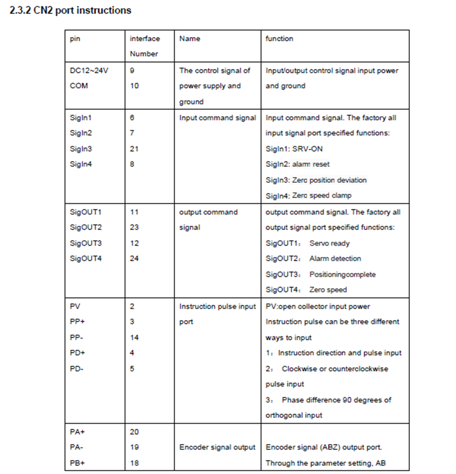
Duet EXP1XD
Red on 5V DRIVER OUT
Green on D0_DIR (-) DRIVER OUT
Black on D0_STEP (-) DRIVER OUT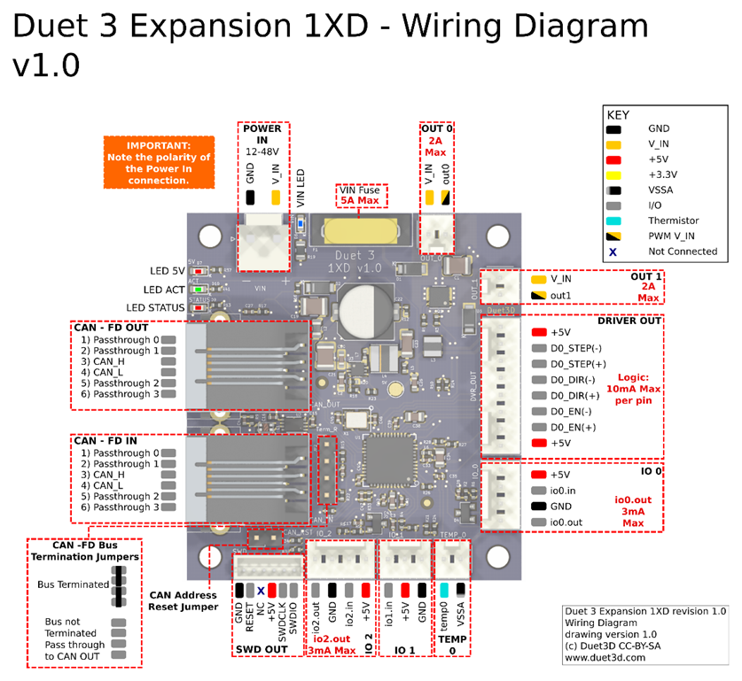
-
I note your config statements don't match the comments. Are the boards all showing up in the object model with the expected addresses (40, 41, 42)? Either the Object Model browser plugin or
M409 K"boards"should list them.(Though your reference to homing and endstops suggests they probably are).
-
@achrn Yes, I'm sorry, I have not change the comments behind the config (noob error) But I confirmed that all addresses are 40,41,42.
-
@Julien30 the extract from the manual that you posted is not clear. Can you provide a link to the complete manual?
-
Hi @dc42 , here is two manual I've got.2012220141540788030.pdf
-
This post is deleted! -
-
@Julien30 thanks. Page 20 of the first document indicates that when using the common PV terminal, you need to provide 24V drive, not 5V as provided by the Duet driver outputs. I suggest you don't connect the PV terminal and instead connect the PP+ and PP- pins to the 1XD Step+ and Step- outputs. Similarly, use PD+ and PD-
-
Hi @dc42, I've done what you suggest. I have diconnect the PV and rewire all my pin.
So now, I have:- driver PP+ to 1XD Step+
- driver PP- to 1XD Step-
- driver PD+ to 1XD Dir +
- driver PD- to 1XD Dir -
I have try to run the motor with DuetWebControl but nothing.
Do you know how can I see if the correct signal is send by the 1XD to the driver when I send orders from DWC ?
I want to know if it's an issue due to the wire, the config of the Duet or my parameters of the driver.
Thank you for your help.
-
@Julien30 said in How to send orders to an servo-driver from Duet?:
Do you know how can I see if the correct signal is send by the 1XD to the driver when I send orders from DWC ?
For the DIR signal it's easy enough: use a multimeter to measure the voltage between DIR+ and DIR-. The polarity should reverse when you reverse the commanded direction.
-
@dc42 Thank you, I have just check it with my multimeter and when I send a command from DWC for run the motor, there is no voltage change between DIR+ and DIR-. I have 4,4V DC every time. So, I think there is a little prob with my config.g, no?
-
@Julien30 said in How to send orders to an servo-driver from Duet?:
@dc42 Thank you, I have just check it with my multimeter and when I send a command from DWC for run the motor, there is no voltage change between DIR+ and DIR-. I have 4,4V DC every time. So, I think there is a little prob with my config.g, no?
Perhaps. I suggest you do the following:
- Check that the red Status LEDs on the 1XD boards are flashing in sync with the Status LED on the main board
- Send command M584 and check that the XYZ axes are mapped to the 1XD boards
- To send a movement command, first send G91 to select relative mode. Then send G1 H2 commands, for example G1 H2 X10 to command 10mm of X movement, and G1 H2 X-10 to command 10mm of reverse X movement.
-
- The red status LEDs on the 1XD boards are flashing in sync with the main board
- After sending M584:
"
M584
Driver assignments: X40.0 Y41.0 Z42.0 E0.1:0.2, 3 axes visible
" - I send G91 and after that I've send G1 H2 X10.
After a while, I've send G1 H2 X50 for testing and G1 H2 X-10.
But every time nothing happen.
When I send all of this command, I also test the DIR PIN with multimeter but as before the voltage stay at 4,4V.
No change with the voltage and no move with the motor.
-
@Julien30 said in How to send orders to an servo-driver from Duet?:
When I send all of this command, I also test the DIR PIN with multimeter but as before the voltage stay at 4,4V.
Are you quite certain that it isn't changing between +4.4V and -4.4V?