G32 keeps exceeding bounds of M557
-
So I've got a delta run by a duet2wifi (hw 1.04, fw 2.05.1, server 1.23) and I've got it set up as follows:
config.g
+++++++++++++++++++++++++++++++++++++++++++++++++++++++++++++++++++++++++++++++++++++++++++++++++++++++++++++++++++++++++; Configuration file for Duet WiFi (firmware version 2.03)
; executed by the firmware on start-up
;
; generated by RepRapFirmware Configuration Tool v3.2.3 on Mon Feb 22 2021 09:18:29 GMT+0000 (Greenwich Mean Time)

; General preferences
G90                                         ; send absolute coordinates...
M83                                         ; ...but relative extruder moves
M550 P"XXXXXXXXX"                           ; set printer name
M665 R105.6 L218 B85 H360                   ; Set delta radius, diagonal rod length, printable radius and homed height
M666 X0 Y0 Z0                               ; put your endstop adjustments here, or let auto calibration find them

; Network
M552 S1                                     ; enable network
M586 P0 S1                                  ; enable HTTP
M586 P1 S0                                  ; disable FTP
M586 P2 S0                                  ; disable Telnet

; Drives
M569 P0 S1                                  ; physical drive 0 goes forwards
M569 P1 S1                                  ; physical drive 1 goes forwards
M569 P2 S1                                  ; physical drive 2 goes forwards
M569 P3 S0                                  ; physical drive 3 goes forwards
M584 X0 Y1 Z2 E3                            ; set drive mapping
M350 X16 Y16 Z16 E16 I1                     ; configure microstepping with interpolation
M92 X100.00 Y100.00 Z100.00 E100.00         ; set steps per mm
M566 X1200.00 Y1200.00 Z1200.00 E1200.00    ; set maximum instantaneous speed changes (mm/min)
M203 X18000.00 Y18000.00 Z18000.00 E1200.00 ; set maximum speeds (mm/min)
M201 X1000.00 Y1000.00 Z1000.00 E1000.00    ; set accelerations (mm/s^2)
M906 X1000 Y1000 Z1000 E1000 I30            ; set motor currents (mA) and motor idle factor in per cent
M84 S30                                     ; Set idle timeout

; Axis Limits
M208 Z-0.1 S1                               ; set minimum Z

; Endstops
M574 X2 Y2 Z2 S1                            ; set active high endstops

; Z-Probe
M558 P5 I1 H10 F120 T6000                   ; set Z probe type to inductive NPN NO type and the dive height + speeds
G31 P500 X20 Y17 Z0.69                      ; set Z probe trigger value, offset and trigger height
M557 X-50:50 Y-50:75 R55 S10                ; define mesh grid

; Heaters
M305 P0 T100000 B4138 R4700                 ; set thermistor + ADC parameters for heater 0
M143 H0 S120                                ; set temperature limit for heater 0 to 120C
M305 P1 T100000 B4725 C7.060000e-8 R4700    ; set thermistor + ADC parameters for heater 1
M143 H1 S286                                ; set temperature limit for heater 1 to 285C

; Fans
M106 P0 C"Hotend Fan" S0 I0 F500 H1 T45     ; set fan 0 name, value, PWM signal inversion and frequency. Thermostatic control is turned on
M106 P1 S1 I0 F500 H-1                      ; set fan 1 value, PWM signal inversion and frequency. Thermostatic control is turned off

; Tools
M563 P0 S"Hotend" D0 H1 F0                  ; define tool 0
;G10 P0 X1.7 Y-0.4 Z0                       ; set tool 0 axis offsets
G10 P0 X0 Y0 Z0                             ; set tool 0 axis offsets
G10 P0 R0 S0                                ; set initial tool 0 active and standby temperatures to 0C

; Custom settings are not defined

; Miscellaneous
T0                                          ; select first tool

M501		                	    ; load config-override.g
M307 H2 A-1 C-1 D-1			    ; map E1 to LEDs
config-override.g
; config-override.g file generated in response to M500 at 2023-02-21 11:55
; This is a system-generated file - do not edit
; Delta parameters
M665 L209.360:209.360:209.360 R106.827 H341.119 B75.0 X3.711 Y10.092 Z0.000
M666 X-3.596 Y1.408 Z2.188 A0.00 B0.00
; Heater model parameters
M307 H0 A90.0 C700.0 D10.0 S1.00 V0.0 B1
M307 H1 A307.7 C241.9 D3.7 S1.00 V11.4 B0
M307 H3 A340.0 C140.0 D5.5 S1.00 V0.0 B0
M307 H4 A340.0 C140.0 D5.5 S1.00 V0.0 B0
M307 H5 A340.0 C140.0 D5.5 S1.00 V0.0 B0
M307 H6 A340.0 C140.0 D5.5 S1.00 V0.0 B0
M307 H7 A340.0 C140.0 D5.5 S1.00 V0.0 B0
G10 L2 P1 X0.00 Y0.00 Z0.00
G10 L2 P2 X0.00 Y0.00 Z0.00
G10 L2 P3 X0.00 Y0.00 Z0.00
G10 L2 P4 X0.00 Y0.00 Z0.00
G10 L2 P5 X0.00 Y0.00 Z0.00
G10 L2 P6 X0.00 Y0.00 Z0.00
G10 L2 P7 X0.00 Y0.00 Z0.00
G10 L2 P8 X0.00 Y0.00 Z0.00
G10 L2 P9 X0.00 Y0.00 Z0.00
So in theory the G32 should not exceed the
R55 S10OR theX-50:50 Y-50:75of the M557, BUT the damned thing keeps on driving the effector into one of the pillars (that's how I broke the effector already once ) Now, the question is - am I doing something wrong and overriding the M557 bounds anywhere, or what? Cause to me it should be pretty straight forward with these boundaries..
Cheers!
-
OMG, is G32 deprecated? I just now realized that the docs say G29 is bound by M557, not G32... Running G29 seems to abide by the mesh defined in M557......

Ref: https://docs.duet3d.com/User_manual/Reference/Gcodes#m557-set-z-probe-point-or-define-probing-grid
Edit: Is there a way for me to remove G32 from the UI, so I (or anybody else) don't use it by mistake?
-
G32 just runs the bed.g macro
What is deprecated is the older form of compensation. G29 and M557 are more flexible and better alternatives to use for that.
In a delta setup your G32/bed.g would still be doing delta calibration. Afterwards you could use G29 to create a heightmap for surface compensation.
-
@vlex G32 is not deprecated. The G30 commands in bed.g are allowed to exceed the normal bed limits, because on delta machines it is advantageous to probe between the towers outside the usual printable bed radius, where the mechanics supports that.
Duet WiFi hardware designer and firmware engineer
Please do not ask me for Duet support via PM or email, use the forum
http://www.escher3d.com, https://miscsolutions.wordpress.com -
The G30 commands in bed.g are allowed to exceed the normal bed limits, because on delta machines it is advantageous to probe between the towers outside the usual printable bed radius, where the mechanics supports that.
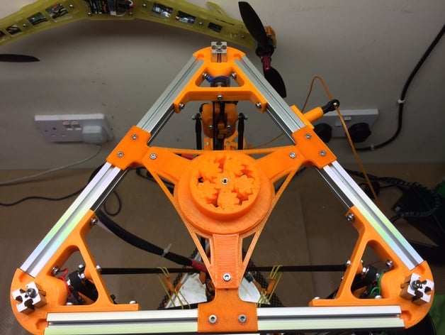
@dc42 Well, this confuses me - I've got a mini kossel and executing G32 is exactly what broke my effector, because a couple of times I wasn't fast enough to hit the emergency break before the effector twisted the rods on one of the axis. Is this meant for only effectors using magnetic joints, or can you give me an example where this probing outside of the printable area won't kill the suspension of the effector like it did mine? If this is not limited to only magnetic suspension it means that either my printer is somehow defective (although it very well might be Layer8, due to the numerous improvements I've done), OR I'm severely overestimating the build radius of my printer...

P.S. Can the orthogonal axis correction in M557 be useful if the pillars geometry is off or askew? Or is it only available for cartesian machines?
P.P.S. and slightly offtopic: Whilst fiddling with the settings, my sd card gave up so I had to work out the fw to get the right DWC and had to get a vanilla configuration from the RRFCT and good that I posted here my config.g, to effectively back it up, lol. This saved me from reconfiguring everything from scratch

-
@vlex whether or not the machine can probe between the towers when outside the usual printing radius, and how far outside it can go, depends on your mechanics and the shape of the bed.
M557 is unlikely to be useful on a delta because if your machine is exhibiting XY skew then it is almost certainly exhibiting distortion too. You can print a pattern of lines in both X and Y directions over the whole bed spaced at e.g. 25mm intervals to check for this.
Duet WiFi hardware designer and firmware engineer
Please do not ask me for Duet support via PM or email, use the forum
http://www.escher3d.com, https://miscsolutions.wordpress.com -
@dc42 That makes sense.
I've got a weird new problem though - after init of the duet, the prints are not great, dare i say even bad - usually there's gaps between the hotend and the bed or sometimes it drags across the bed. After running G29 it seems to work slightly better, BUT as soon as I run G32 I think the geometry goes right out of the window. I'm trying to print a spool holder and one of the parts is a big triangle with a circle inside it:
All is good and dandy until the G32, after it all of the sudden the circle becomes an ellipse and a quite elongated one. I'm assuming something ain't right in the setup above (I'm reusing it except I added springs under the bolts of the bed so it's now about 10-12mm higher, so the Z-height is less now). The elongation is across practically the Y-axis (imagine a line between the furthermost pillar on the pic above and the centre of the section).Any ideas what I'm doing wrong OR how to troubleshoot this? Thanks in advance!
-
@vlex can you post your bed.g?
-
@jay_s_uk sure thing:
; called to perform automatic delta calibration via G32
;
; generated by RepRapFirmware Configuration Tool v3.3.15 on Fri Feb 24 2023 13:57:20 GMT+0000 (Greenwich Mean Time)
M561 ; clear any bed transform
G28  ; home all towers
; Probe the bed at 3 peripheral and 3 halfway points, and perform 6-factor auto compensation
; Before running this, you should have set up your Z-probe trigger height to suit your build, in the G31 command in config.g.
G30 P0 X0 Y40.43 H0 Z-99999
G30 P1 X38.22 Y-22.07 H0 Z-99999
G30 P2 X-47.63 Y-27.5 H0 Z-99999
G30 P3 X0 Y15.47 H0 Z-99999
G30 P4 X14.87 Y-8.59 H0 Z-99999
G30 P5 X-23.82 Y-13.75 H0 Z-99999
G30 P6 X0 Y0 H0 Z-99999 S6
; Use S-1 for measurements only, without calculations. Use S4 for endstop heights and Z-height only. Use S6 for full 6 factors
; If your Z probe has significantly different trigger heights depending on XY position, adjust the H parameters in the G30 commands accordingly. The value of each H parameter should be (trigger height at that XY position) - (trigger height at centre of bed)
The diff between the posted above
config.gand the current one is here:;Current ; Previously posted ; Set delta radius, diagonal rod length, printable radius and homed height M665 R105.6 L218 B85 H333.5 ; M665 R105.6 L218 B85 H360 ; define mesh grid M557 X-50:50 Y-50:75 R75 S20 ;M557 X-50:50 Y-50:75 R55 S10Atm there's no
config-override.gso not posting one and theheightmap.csvatm looks like this (not sure whether it helps for me to post it, but can't hurt, can it?):RepRapFirmware height map file v2, min error -1.601, max error 1.398, mean -0.163, deviation 0.747 xmin,xmax,ymin,ymax,radius,xspacing,yspacing,xnum,ynum -50.00,50.00,-50.00,75.00,75.00,20.00,20.00,6,7 0, -0.896, -1.552, -1.479, -1.331, -0.823 -0.137, -0.397, -0.472, -0.389, -0.280, -0.023 0.056, -0.385, -0.198, -0.004, 0.360, 0.852 0.284, 0.220, 0.220, 0.329, 0.729, 1.180 -0.159, -0.699, -0.389, 0.082, 0.683, 1.398 -0.782, -0.665, -0.476, -0.190, 0.501, 1.342 0, 0, -1.601, -0.950, 0, 0 -
@vlex nothing jumps out at me as looking wrong.
Maybe it's time to take the plunge and update to 3.4.5?Owns various duet boards and is the main wiki maintainer for the Teamgloomy LPC/STM32 port of RRF. Assume I'm running whatever the latest beta/stable build is
-
@vlex what type of Z probe do you have?
Duet WiFi hardware designer and firmware engineer
Please do not ask me for Duet support via PM or email, use the forum
http://www.escher3d.com, https://miscsolutions.wordpress.com -
@dc42 it's an inductive LJ12A3-4-Z/BX. From what I've tested it triggers consistently at 0.69 height for the nozzle (the sensor is higher than the nozzle by another 0.4mm or so).
-
@jay_s_uk if i did that, would i be able to reuse my config? Also I tried upgrading when my sd card gave out, but nothing worked, so i had to revert to whatever fw i had and a compatible dwc.
-
@vlex there would be some changes required but it wouldn't be insurmountable.
-
@vlex said in G32 keeps exceeding bounds of M557:
All is good and dandy until the G32, after it all of the sudden the circle becomes an ellipse and a quite elongated one
are you 100% sure you have the probe offsets correct? if you have the probe XY offsets wrong that could explain some of the behaviour you are seeing.