Duet3D Logo Duet3D
    • Tags
    • Documentation
    • Order
    • Register
    • Login
    1. Home
    2. vlex
    • Profile
    • Following 0
    • Followers 0
    • Topics 5
    • Posts 21
    • Best 1
    • Controversial 0
    • Groups 0

    vlex

    @vlex

    1
    Reputation
    1
    Profile views
    21
    Posts
    0
    Followers
    0
    Following
    Joined Last Online

    vlex Unfollow Follow

    Best posts made by vlex

    • RE: Duet2Wifi weird extruder jitter

      The new volcano arrived a couple of days ago and I just finished assembling and reconfiguring the config.g to the new dimensions - the jitter turns out as suspected was due to a blockage in either the cold side or the heatbreak. Either way the new hotend now works just fine, except there's obviously some geometry quirks i need to take care (in a separate thread though).

      This matter could be considered resolved. Thanks for the help!

      posted in Duet Hardware and wiring
      vlexundefined
      vlex

    Latest posts made by vlex

    • RE: G32 keeps exceeding bounds of M557

      @jay_s_uk if i did that, would i be able to reuse my config? Also I tried upgrading when my sd card gave out, but nothing worked, so i had to revert to whatever fw i had and a compatible dwc.

      posted in Tuning and tweaking
      vlexundefined
      vlex
    • RE: G32 keeps exceeding bounds of M557

      @dc42 it's an inductive LJ12A3-4-Z/BX. From what I've tested it triggers consistently at 0.69 height for the nozzle (the sensor is higher than the nozzle by another 0.4mm or so).

      posted in Tuning and tweaking
      vlexundefined
      vlex
    • RE: G32 keeps exceeding bounds of M557

      @jay_s_uk sure thing:

      ; called to perform automatic delta calibration via G32
      ;
      ; generated by RepRapFirmware Configuration Tool v3.3.15 on Fri Feb 24 2023 13:57:20 GMT+0000 (Greenwich Mean Time)
      M561 ; clear any bed transform
      G28  ; home all towers
      ; Probe the bed at 3 peripheral and 3 halfway points, and perform 6-factor auto compensation
      ; Before running this, you should have set up your Z-probe trigger height to suit your build, in the G31 command in config.g.
      G30 P0 X0 Y40.43 H0 Z-99999
      G30 P1 X38.22 Y-22.07 H0 Z-99999
      G30 P2 X-47.63 Y-27.5 H0 Z-99999
      G30 P3 X0 Y15.47 H0 Z-99999
      G30 P4 X14.87 Y-8.59 H0 Z-99999
      G30 P5 X-23.82 Y-13.75 H0 Z-99999
      G30 P6 X0 Y0 H0 Z-99999 S6
      ; Use S-1 for measurements only, without calculations. Use S4 for endstop heights and Z-height only. Use S6 for full 6 factors
      ; If your Z probe has significantly different trigger heights depending on XY position, adjust the H parameters in the G30 commands accordingly. The value of each H parameter should be (trigger height at that XY position) - (trigger height at centre of bed)
      

      The diff between the posted above config.g and the current one is here:

      ;Current                                    ; Previously posted
      ; Set delta radius, diagonal rod length, printable radius and homed height
      M665 R105.6 L218 B85 H333.5                 ; M665 R105.6 L218 B85 H360
      
      ; define mesh grid
      M557 X-50:50 Y-50:75 R75 S20                ;M557 X-50:50 Y-50:75 R55 S10
      

      Atm there's no config-override.g so not posting one and the heightmap.csv atm looks like this (not sure whether it helps for me to post it, but can't hurt, can it?):

      RepRapFirmware height map file v2, min error -1.601, max error 1.398, mean -0.163, deviation 0.747
      xmin,xmax,ymin,ymax,radius,xspacing,yspacing,xnum,ynum
      -50.00,50.00,-50.00,75.00,75.00,20.00,20.00,6,7
            0, -0.896, -1.552, -1.479, -1.331, -0.823
       -0.137, -0.397, -0.472, -0.389, -0.280, -0.023
        0.056, -0.385, -0.198, -0.004,  0.360,  0.852
        0.284,  0.220,  0.220,  0.329,  0.729,  1.180
       -0.159, -0.699, -0.389,  0.082,  0.683,  1.398
       -0.782, -0.665, -0.476, -0.190,  0.501,  1.342
            0,      0, -1.601, -0.950,      0,      0
      
      posted in Tuning and tweaking
      vlexundefined
      vlex
    • RE: G32 keeps exceeding bounds of M557

      @dc42 That makes sense.

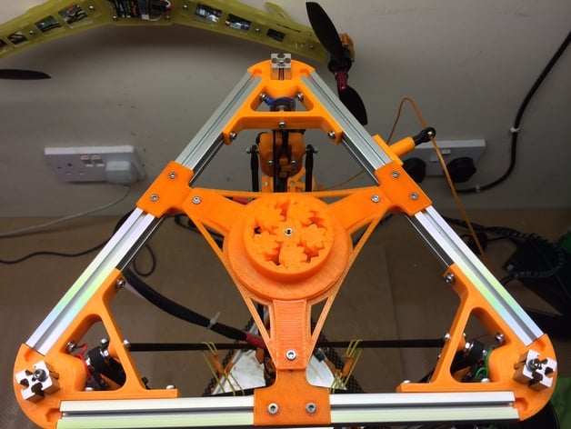
      I've got a weird new problem though - after init of the duet, the prints are not great, dare i say even bad - usually there's gaps between the hotend and the bed or sometimes it drags across the bed. After running G29 it seems to work slightly better, BUT as soon as I run G32 I think the geometry goes right out of the window. I'm trying to print a spool holder and one of the parts is a big triangle with a circle inside it:

      All is good and dandy until the G32, after it all of the sudden the circle becomes an ellipse and a quite elongated one. I'm assuming something ain't right in the setup above (I'm reusing it except I added springs under the bolts of the bed so it's now about 10-12mm higher, so the Z-height is less now). The elongation is across practically the Y-axis (imagine a line between the furthermost pillar on the pic above and the centre of the section).

      Any ideas what I'm doing wrong OR how to troubleshoot this? Thanks in advance!

      posted in Tuning and tweaking
      vlexundefined
      vlex
    • RE: G32 keeps exceeding bounds of M557

      The G30 commands in bed.g are allowed to exceed the normal bed limits, because on delta machines it is advantageous to probe between the towers outside the usual printable bed radius, where the mechanics supports that.

      @dc42 Well, this confuses me - I've got a mini kossel and executing G32 is exactly what broke my effector, because a couple of times I wasn't fast enough to hit the emergency break before the effector twisted the rods on one of the axis. Is this meant for only effectors using magnetic joints, or can you give me an example where this probing outside of the printable area won't kill the suspension of the effector like it did mine? If this is not limited to only magnetic suspension it means that either my printer is somehow defective (although it very well might be Layer8, due to the numerous improvements I've done), OR I'm severely overestimating the build radius of my printer... 😰

      P.S. Can the orthogonal axis correction in M557 be useful if the pillars geometry is off or askew? Or is it only available for cartesian machines?

      P.P.S. and slightly offtopic: Whilst fiddling with the settings, my sd card gave up so I had to work out the fw to get the right DWC and had to get a vanilla configuration from the RRFCT and good that I posted here my config.g, to effectively back it up, lol. This saved me from reconfiguring everything from scratch 😅

      posted in Tuning and tweaking
      vlexundefined
      vlex
    • RE: G32 keeps exceeding bounds of M557

      OMG, is G32 deprecated? I just now realized that the docs say G29 is bound by M557, not G32... Running G29 seems to abide by the mesh defined in M557...... 🤦

      Ref: https://docs.duet3d.com/User_manual/Reference/Gcodes#m557-set-z-probe-point-or-define-probing-grid

      Edit: Is there a way for me to remove G32 from the UI, so I (or anybody else) don't use it by mistake?

      posted in Tuning and tweaking
      vlexundefined
      vlex
    • G32 keeps exceeding bounds of M557

      So I've got a delta run by a duet2wifi (hw 1.04, fw 2.05.1, server 1.23) and I've got it set up as follows:

      config.g

      +++++++++++++++++++++++++++++++++++++++++++++++++++++++++++++++++++++++++++++++++++++++++++++++++++++++++++++++++++++++++; Configuration file for Duet WiFi (firmware version 2.03)
      ; executed by the firmware on start-up
      ;
      ; generated by RepRapFirmware Configuration Tool v3.2.3 on Mon Feb 22 2021 09:18:29 GMT+0000 (Greenwich Mean Time)
      
      ; General preferences
      G90                                         ; send absolute coordinates...
      M83                                         ; ...but relative extruder moves
      M550 P"XXXXXXXXX"                           ; set printer name
      M665 R105.6 L218 B85 H360                   ; Set delta radius, diagonal rod length, printable radius and homed height
      M666 X0 Y0 Z0                               ; put your endstop adjustments here, or let auto calibration find them
      
      ; Network
      M552 S1                                     ; enable network
      M586 P0 S1                                  ; enable HTTP
      M586 P1 S0                                  ; disable FTP
      M586 P2 S0                                  ; disable Telnet
      
      ; Drives
      M569 P0 S1                                  ; physical drive 0 goes forwards
      M569 P1 S1                                  ; physical drive 1 goes forwards
      M569 P2 S1                                  ; physical drive 2 goes forwards
      M569 P3 S0                                  ; physical drive 3 goes forwards
      M584 X0 Y1 Z2 E3                            ; set drive mapping
      M350 X16 Y16 Z16 E16 I1                     ; configure microstepping with interpolation
      M92 X100.00 Y100.00 Z100.00 E100.00         ; set steps per mm
      M566 X1200.00 Y1200.00 Z1200.00 E1200.00    ; set maximum instantaneous speed changes (mm/min)
      M203 X18000.00 Y18000.00 Z18000.00 E1200.00 ; set maximum speeds (mm/min)
      M201 X1000.00 Y1000.00 Z1000.00 E1000.00    ; set accelerations (mm/s^2)
      M906 X1000 Y1000 Z1000 E1000 I30            ; set motor currents (mA) and motor idle factor in per cent
      M84 S30                                     ; Set idle timeout
      
      ; Axis Limits
      M208 Z-0.1 S1                               ; set minimum Z
      
      ; Endstops
      M574 X2 Y2 Z2 S1                            ; set active high endstops
      
      ; Z-Probe
      M558 P5 I1 H10 F120 T6000                   ; set Z probe type to inductive NPN NO type and the dive height + speeds
      G31 P500 X20 Y17 Z0.69                      ; set Z probe trigger value, offset and trigger height
      M557 X-50:50 Y-50:75 R55 S10                ; define mesh grid
      
      ; Heaters
      M305 P0 T100000 B4138 R4700                 ; set thermistor + ADC parameters for heater 0
      M143 H0 S120                                ; set temperature limit for heater 0 to 120C
      M305 P1 T100000 B4725 C7.060000e-8 R4700    ; set thermistor + ADC parameters for heater 1
      M143 H1 S286                                ; set temperature limit for heater 1 to 285C
      
      ; Fans
      M106 P0 C"Hotend Fan" S0 I0 F500 H1 T45     ; set fan 0 name, value, PWM signal inversion and frequency. Thermostatic control is turned on
      M106 P1 S1 I0 F500 H-1                      ; set fan 1 value, PWM signal inversion and frequency. Thermostatic control is turned off
      
      ; Tools
      M563 P0 S"Hotend" D0 H1 F0                  ; define tool 0
      ;G10 P0 X1.7 Y-0.4 Z0                       ; set tool 0 axis offsets
      G10 P0 X0 Y0 Z0                             ; set tool 0 axis offsets
      G10 P0 R0 S0                                ; set initial tool 0 active and standby temperatures to 0C
      
      ; Custom settings are not defined
      
      ; Miscellaneous
      T0                                          ; select first tool
      
      M501		                	    ; load config-override.g
      M307 H2 A-1 C-1 D-1			    ; map E1 to LEDs
      

      config-override.g

      ; config-override.g file generated in response to M500 at 2023-02-21 11:55
      ; This is a system-generated file - do not edit
      ; Delta parameters
      M665 L209.360:209.360:209.360 R106.827 H341.119 B75.0 X3.711 Y10.092 Z0.000
      M666 X-3.596 Y1.408 Z2.188 A0.00 B0.00
      ; Heater model parameters
      M307 H0 A90.0 C700.0 D10.0 S1.00 V0.0 B1
      M307 H1 A307.7 C241.9 D3.7 S1.00 V11.4 B0
      M307 H3 A340.0 C140.0 D5.5 S1.00 V0.0 B0
      M307 H4 A340.0 C140.0 D5.5 S1.00 V0.0 B0
      M307 H5 A340.0 C140.0 D5.5 S1.00 V0.0 B0
      M307 H6 A340.0 C140.0 D5.5 S1.00 V0.0 B0
      M307 H7 A340.0 C140.0 D5.5 S1.00 V0.0 B0
      G10 L2 P1 X0.00 Y0.00 Z0.00
      G10 L2 P2 X0.00 Y0.00 Z0.00
      G10 L2 P3 X0.00 Y0.00 Z0.00
      G10 L2 P4 X0.00 Y0.00 Z0.00
      G10 L2 P5 X0.00 Y0.00 Z0.00
      G10 L2 P6 X0.00 Y0.00 Z0.00
      G10 L2 P7 X0.00 Y0.00 Z0.00
      G10 L2 P8 X0.00 Y0.00 Z0.00
      G10 L2 P9 X0.00 Y0.00 Z0.00
      

      So in theory the G32 should not exceed the R55 S10 OR the X-50:50 Y-50:75 of the M557, BUT the damned thing keeps on driving the effector into one of the pillars (that's how I broke the effector already once 😠 ) Now, the question is - am I doing something wrong and overriding the M557 bounds anywhere, or what? Cause to me it should be pretty straight forward with these boundaries..

      Cheers!

      posted in Tuning and tweaking
      vlexundefined
      vlex
    • RE: D2WF induct Zprobe wiring - won't the high voltage fry my duet?

      Thanks @dc42 FWIW I did end up wiring it as show in the diagram before waiting for input here it didn't fry the board, so I was happy for a while. Then configured the zprobe correctly, spent like 2 hours correcting the geometry and adding setting to the gcode so it works and it finally did, BUT THEN I broke the effector, so I'm back at square one. I'm logging here the links I used for posterity and for the off chance someone else is in my shoes in the future:

      https://duet3d.dozuki.com/Wiki/Connecting_a_Z_probe#Section_Overview
      https://duet3d.dozuki.com/Wiki/Test_and_calibrate_the_Z_probe
      https://duet3d.dozuki.com/Wiki/G32
      https://duet3d.dozuki.com/Wiki/Calibrating_a_delta_printer#Section_Auto_calibration
      https://docs.duet3d.com/User_manual/Reference/Gcodes

      Alas the new docs don't have any of the useful steps in the old ones, but good they're still there.

      I guess the thread can be closed..

      posted in Duet Hardware and wiring
      vlexundefined
      vlex
    • D2WF induct Zprobe wiring - won't the high voltage fry my duet?

      Howdy all. It's been a while since I've played with my duet delta and finally got around to printing myself a new better effector with a slot for an inductive zprobe: https://www.thingiverse.com/thing:4571352

      Now I'm a bit confused about the wiring: it is an LJ12A3-4-Z/BX which is an NPN NO inductive sensor, according to its specs takes 10-30VIN, HOWEVER, I'm a bit confused with the wiring of the kagigger to my duet2 wifi (v1.04):

      • I wired the brown to board VCC (+12V)
      • I wired the blue to board VDD (GND)
      • The remaining black is the sense, which according to the wiring diagram on the old docs page says SHOULD be capable of being wired directly into the ZPROBE_IN on the header (wiring diagram pic):

      But I AM a bit worried wiring the ZPROBE directly. For a while I was thinking of putting in like a buck converter in line to drop it to 3.3V, but wanted to doublecheck with y'all whether this should be okay as-is @12V operational voltage for the probe.

      Also I was gonna ask why the hell it also keeps on showing ZProbe 1000 on the UI, and then remembered I hadn't reconfigured the duet from the old limit switch (doh). So I'm gonna fix the config and report again. Hope I don't burn the board in the process 😬

      Cheers,
      V

      posted in Duet Hardware and wiring
      vlexundefined
      vlex
    • RE: Duet2WiFi net connection inconsistent between VIN and USB

      It connects to the network with the strongest signal.

      @Phaedrux that's great to know. That said, in my case it caused issues and if this were documented anywhere it would've helped me solve my issue a lot sooner.

      posted in Duet Hardware and wiring
      vlexundefined
      vlex