9 axis CNC Mill-Turn Center (professional build)
-
@Generic-Default this is fantastic to see! Will be in touch.
-
@Generic-Default wow, amazing build! And great work.
Ian
-
@Generic-Default that's great! Can you tell us more about the custom transfer board, and what changes you had to make to RRF?
Duet WiFi hardware designer and firmware engineer
Please do not ask me for Duet support via PM or email, use the forum
http://www.escher3d.com, https://miscsolutions.wordpress.com -
Truly impressive!
-
@dc42
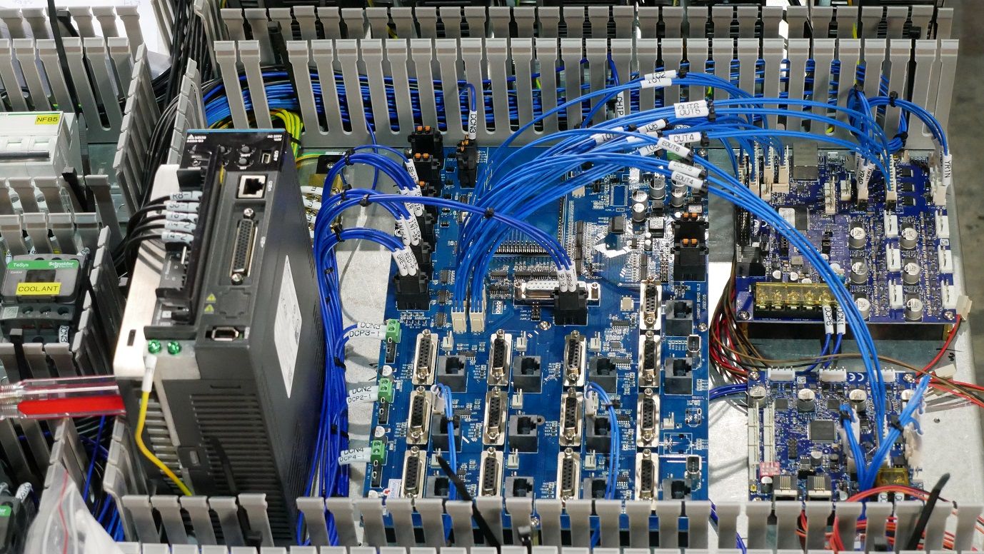
Here's up close.The purpose of the transfer board is to take the step/dir signals from the Duet and pass them on to the servo drivers. It has all the connectors for the servo drivers (see the RJ jacks for each servo driver) with both digital and analog communication, and at the top of this transfer board there's an Arduino due in the open rectangular spot (not mounted in this picture). The transfer board also hosts a lot of the I/O pins and has rugged industrial connectors.
One concern I have with the Duet design is that we have to manually solder wires to each step/dir output on the back of the Duet board and expansion. I wish it had regular 0.1mm pins. A big concern has always been missed steps due to noise, I believe we ended up putting opto-isolators or digital isolators on every one of these to prevent noise on the step/dir stuff.
We are currently on RepRap firmware 3.3 and an older build of the DWC. Our code projects have become much more complex than I'd like. In the beginning, I wanted to mount the Duet on standoffs directly on the big transfer board, but the Duet CAN bus had protocol problems when we tried to integrate it, so we ended up using an Arduino as an intermediary, but of course this made everything more complex.
I'd be open to sharing the whole transfer board project as open source if it could be managed better than we can do. Right now I am a bit hesitant of putting it all online as open source because I think it needs a team of programmers to really understand and integrate, if I just dump the code online I doubt anyone could make use of it.
This is the 3rd iteration of the transfer board design that we did a formal PCB run with. We have 5 of these with components soldered and 5 more without. I'll try to post a video of the DWC modifications we made as well; they are useful for CNC but not 3d printing.
-
@Generic-Default A very different machine than the SwissMak 210
-
@fishgrog Actually, it's almost the same as far as function and operations go. The MT900 just has a larger work envelope and side mount ATC. The user interface is almost identical. If you run the exact same program for turning and milling on the two different machines, they will make the same part. The MT210 uses the previous version of the same transfer board for the servos, and other than differences in the Arduino firmware and config files, they are basically the same thing.
The MT900 has much larger cast iron structures and a big enclosure of course. They look very different but do the same thing.
-
@Generic-Default thanks for providing more detail.
Have you seen our MB6XD board, https://docs.duet3d.com/Duet3D_hardware/Duet_3_family/Duet_3_Mainboard_6XD_Hardware_Overview ? It's designed for systems that use external servos and so don't need any on-board drivers. It provides six sets of 5V level open-drain step/dir/enable outputs. Most servos have optically isolated step/dir/enable inputs, so additional isolation is not normally required.
-
I don't know if I could be any more excited to see this post! Excellent work, will be super beneficial to the community using Duet/RRF controls on CNC machines. I was actually starting to develop some integrations for tool management in DWC but I am curious to see how you integrated it on your system. Regardless, blown away by the polish and the thought that went into this and I hope you get plenty of interest and win the most innovative machine award.
Thanks for sharing and I hope you get the attention you deserve, and I am excited to see stuff like this being done with RRF!
-
@Generic-Default, this looks like an interesting project. As somebody who has owned a CNC machine shop, I'm curious... Are your encoders on the motors, or are they linear encoders? If the former, how do you handle backlash adjustment?
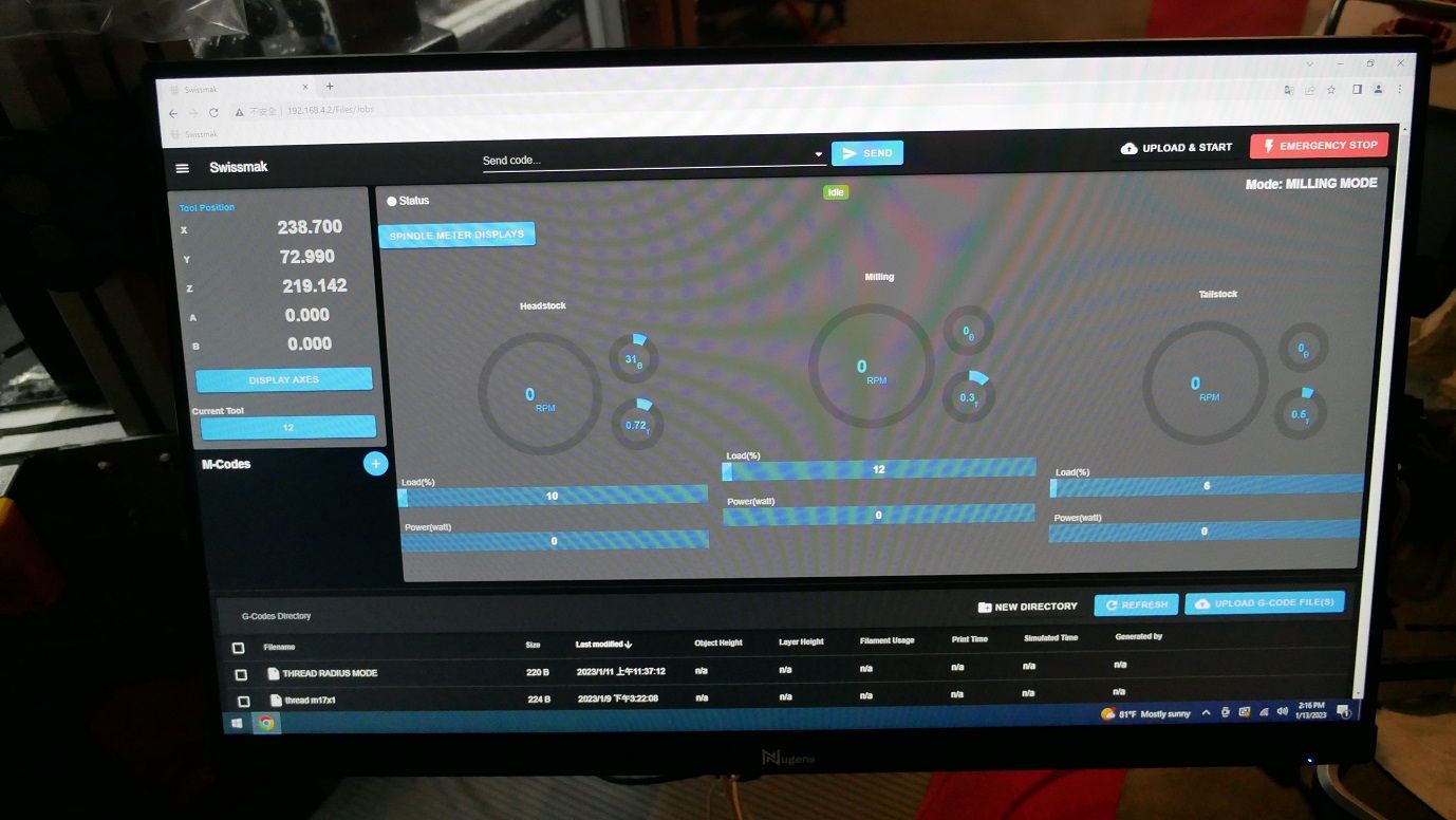
Can you do g-code modifications on the machine?
Did you fix the pause (m0 &m1) so they function like real cnc machines?I've used the duet boards on a few little jigs, but for more complicated machines, I stuck with Linux CNC... Primarily, to avoid bringing the duet up to industry standard. Kudos to you for making it happen!
-
@tenaja The Duet uses the stepper motor drivers directly on the board - we took the step/dir outputs from these and use them to control full sized AC servos from Delta electronics - exactly like a Fanuc or equivalent AC servo. They have 22, 23, or 24 bit encoders on them, which are no absolute, but act like absolute after finding the index pulse.
We are likely to switch to Absolute encoders in the future to avoid homing. For now, when the machine is turned on, it needs to be homed like a 3d printer, this takes about 30 seconds. It doesn't use limit switches to do this, rather it just goes until the servo driver detects a stall, then backs off to the nearest index pulse. This gives perfect repeatability to the micron.
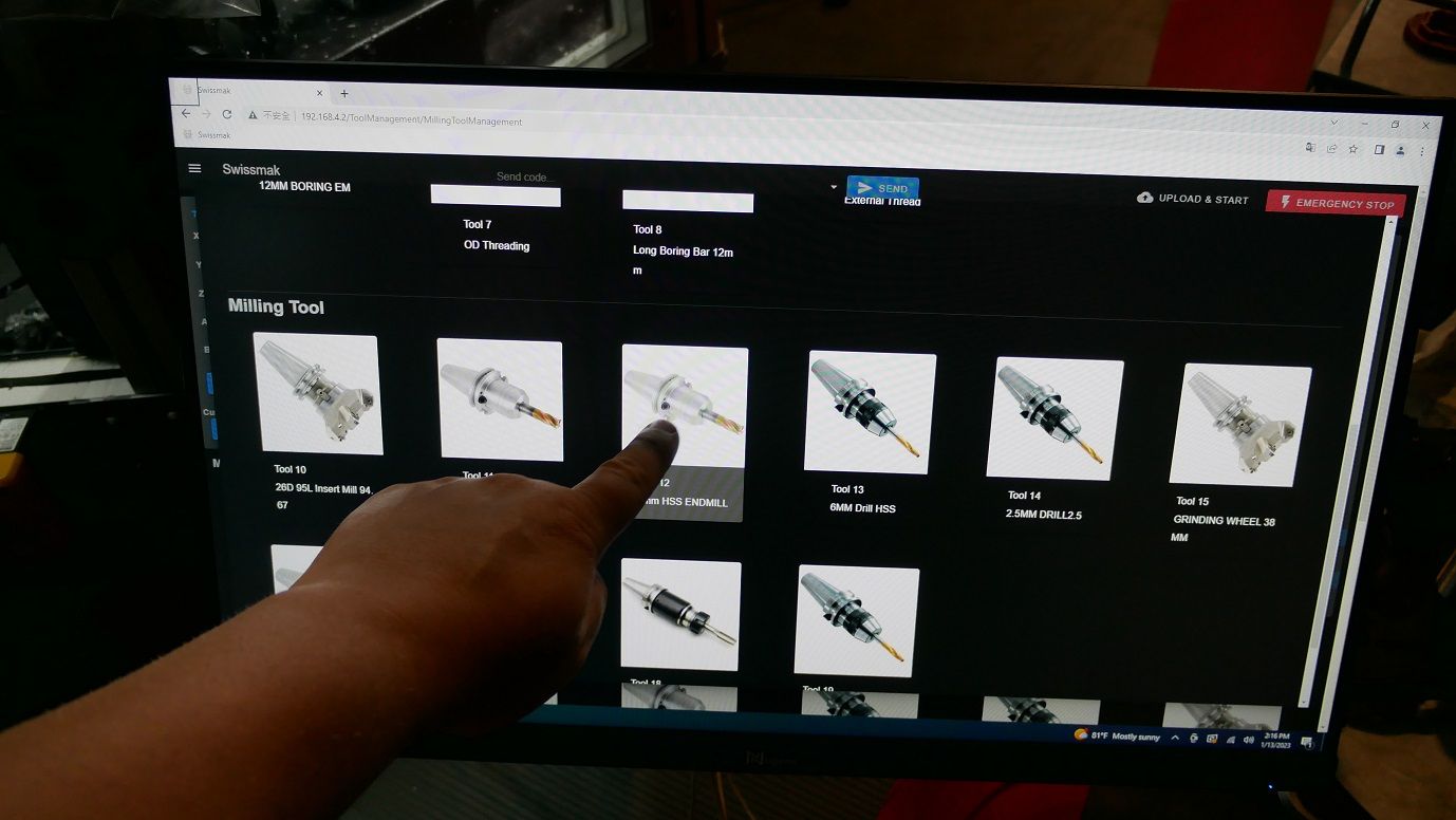
Yes, it has functions like M19 spindle orient, M8 coolant, G72 threading, G84 rigid tapping, all that. It also has a 24 tool ATC side mounted with accessibility through the operator door.
As far as backlash, we are using Hiwin ballscrews and a typical angular contact setup. The backlash is under 1 micron, so we don't need to adjust it. We did create a backlash firmware feature (which is now unnecessary in Duet firmware 3.5+) but the mechanical backlash of each axis is negligible so we just set it to zero.
Here's the calibration video, showing the accuracy. (is there a way to make the video show up as embedded?)
-
@Generic-Default do you have a link to your fork of the duet firmware?