Duet3D Logo Duet3D
    • Tags
    • Documentation
    • Order
    • Register
    • Login

    SSR controlled heater setup query

    Scheduled Pinned Locked Moved
    General Discussion
    4
    30
    926
    Loading More Posts
    • Oldest to Newest
    • Newest to Oldest
    • Most Votes
    Reply
    • Reply as topic
    Log in to reply
    This topic has been deleted. Only users with topic management privileges can see it.
    • 900turboundefined
      900turbo @900turbo
      last edited by

      @900turbo 91063526-1AB1-4C21-B1C1-CAF2BDAC8ABF.jpeg

      droftartsundefined 1 Reply Last reply Reply Quote 0
      • droftartsundefined
        droftarts administrators @900turbo
        last edited by

        @900turbo That looks fine. Like I said, you can use pretty much any I/O out pin (though it is slightly more complicated on the 6XD because of the opto isolated outputs), and the PSON pin is basically just another switchable pin.

        Ian

        Bed-slinger - Mini5+ WiFi/1LC | RRP Fisher v1 - D2 WiFi | Polargraph - D2 WiFi | TronXY X5S - 6HC/Roto | CNC router - 6HC | Tractus3D T1250 - D2 Eth

        900turboundefined 1 Reply Last reply Reply Quote 0
        • 900turboundefined
          900turbo @droftarts
          last edited by

          @droftarts Just thought I would check.
          Thanks for the help Ian.

          1 Reply Last reply Reply Quote 0
          • 900turboundefined
            900turbo @droftarts
            last edited by 900turbo

            @droftarts
            I took the readings at 200ohms

            Room temperature 30.2

            25 degrees = 30.1

            50 degrees = 30.0

            70 degrees = 30.1

            so only a very slight drop in resistance followed by a rise not sure what this means ?

            droftartsundefined 1 Reply Last reply Reply Quote 0
            • droftartsundefined
              droftarts administrators @900turbo
              last edited by

              @900turbo said in SSR controlled heater setup query:

              I took the readings at 200ohms

              I don't know what you mean by that? Do you mean you get 200 x 30 = 6000 ohms? I'm used to modern digital multimeters!

              Check you are measuring the resistance of the temperature sensor, by measuring ohms across the two wires that come from the bed. Looking at your picture of the bed, these are the red wires. The second pair of wires, the thicker white ones, are for the heater. Usually, these will be low resistance. Check you're measuring the correct wires, they will be the thinner ones.

              For a 100k thermistor, you should get something like:
              25 degrees = ~100k ohms
              50 degrees = ~33K ohms
              70 degrees = ~15k ohms

              Ian

              Bed-slinger - Mini5+ WiFi/1LC | RRP Fisher v1 - D2 WiFi | Polargraph - D2 WiFi | TronXY X5S - 6HC/Roto | CNC router - 6HC | Tractus3D T1250 - D2 Eth

              900turboundefined 1 Reply Last reply Reply Quote 0
              • 900turboundefined
                900turbo @droftarts
                last edited by

                @droftarts 8A671DA4-1278-41E9-BC40-FCC4C8DB952A.jpeg I mean this as in 200 set on the multi meter , there are 5 pins on the heater bed loom of which only 2 produce a reading so I assumed it’s temp sensors wires

                Thank you

                droftartsundefined 1 Reply Last reply Reply Quote 0
                • droftartsundefined
                  droftarts administrators @900turbo
                  last edited by

                  @900turbo can you show a picture of the 5 pins? Try setting the meter to 20k or 200k.

                  Ian

                  Bed-slinger - Mini5+ WiFi/1LC | RRP Fisher v1 - D2 WiFi | Polargraph - D2 WiFi | TronXY X5S - 6HC/Roto | CNC router - 6HC | Tractus3D T1250 - D2 Eth

                  900turboundefined 1 Reply Last reply Reply Quote 0
                  • 900turboundefined
                    900turbo @droftarts
                    last edited by

                    @droftarts at 20 and 200k I don’t get a reading just 0.00

                    900turboundefined 1 Reply Last reply Reply Quote 0
                    • 900turboundefined
                      900turbo @900turbo
                      last edited by

                      @900turbo A1749DBC-C6BE-43FD-8C1A-E2DF8508E134.jpeg

                      deckingmanundefined 1 Reply Last reply Reply Quote 0
                      • deckingmanundefined
                        deckingman @900turbo
                        last edited by

                        @900turbo 30 Ohms sounds more like the heater resistance than a temperature sensor. Is it 110V mains or 240V? If it's 240V then using ohms law, 30 Ohms would mean it draws 8 Amps which is about 2,000 watts. If its 110V then 30 Ohms would mean about 3.7 Amps giving about 400 Watts. Do either of those wattage figures sound like the spec for your heater? If so, that confirms that you are measuring the heater resistance, not the temperature sensor. If that's the case, try again with your meter set to read 200K.

                        Ian
                        https://somei3deas.wordpress.com/
                        https://www.youtube.com/@deckingman

                        900turboundefined 1 Reply Last reply Reply Quote 1
                        • 900turboundefined
                          900turbo @deckingman
                          last edited by

                          @deckingman
                          The heater draws power straight from the PSU at 100-240V so I'm not sure what it draws. However I tried what you said using 200K and got the following results
                          25 degrees = 128.9
                          50 degrees = 38.0
                          70 degrees = 19.0

                          Thanks for the help!

                          droftartsundefined deckingmanundefined 2 Replies Last reply Reply Quote 0
                          • droftartsundefined
                            droftarts administrators @900turbo
                            last edited by

                            @900turbo With those results, I'd say it was a 100k NTC thermistor, which uses a beta value of 3950. So use:

                            M308 S0 P"temp0" Y"thermistor" T100000 B3950
                            

                            For more information on thermistor parameters, see https://docs.duet3d.com/User_manual/Connecting_hardware/Temperature_connecting_thermistors_PT1000#typical-parameter-values

                            Ian

                            Bed-slinger - Mini5+ WiFi/1LC | RRP Fisher v1 - D2 WiFi | Polargraph - D2 WiFi | TronXY X5S - 6HC/Roto | CNC router - 6HC | Tractus3D T1250 - D2 Eth

                            900turboundefined 1 Reply Last reply Reply Quote 2
                            • deckingmanundefined
                              deckingman @900turbo
                              last edited by

                              @900turbo said in SSR controlled heater setup query:

                              @deckingman
                              The heater draws power straight from the PSU at 100-240V so I'm not sure what it draws. ........................

                              What I meant was, do you happen to know the wattage of the heater? From Ohms law, if we know the voltage and the resistance, we can calculate the current draw and then voltage x current = wattage. But anyway, it sounds like you've now found the correct pair of wires for the temperature sensor........

                              Ian
                              https://somei3deas.wordpress.com/
                              https://www.youtube.com/@deckingman

                              1 Reply Last reply Reply Quote 1
                              • 900turboundefined
                                900turbo @droftarts
                                last edited by

                                @droftarts When I use the calculator i get6cecdae5-cb9e-418b-9cde-c2fbe9a5a236-image.png 
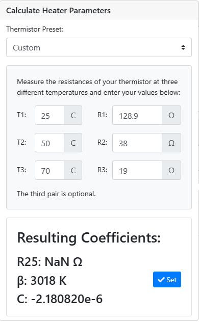
a beta value of 3018 should I use this or 3950 ?

                                jay_s_ukundefined droftartsundefined 2 Replies Last reply Reply Quote 0
                                • jay_s_ukundefined
                                  jay_s_uk @900turbo
                                  last edited by

                                  @900turbo use 3950

                                  Owns various duet boards and is the main wiki maintainer for the Teamgloomy LPC/STM32 port of RRF. Assume I'm running whatever the latest beta/stable build is

                                  900turboundefined 1 Reply Last reply Reply Quote 1
                                  • 900turboundefined
                                    900turbo @jay_s_uk
                                    last edited by

                                    @jay_s_uk Thank You.

                                    1 Reply Last reply Reply Quote 0
                                    • droftartsundefined
                                      droftarts administrators @900turbo
                                      last edited by

                                      @900turbo Use 3950 to start with. If it proves to be inaccurate, you can recalibrate it later.

                                      If I put your data into the thermistor calculator here https://www.thinksrs.com/downloads/programs/therm calc/ntccalibrator/ntccalculator.html and then set the Beta model coefficients for 100k NTC with Beta 3950, your 50C and 70C results match the curve well, but the 25C result is out. I'd guess that this result is inaccurate; either your meter is reading erroneously, or the temperature is closer to 20C rather than 25C. Most thermistors are 100k at 25C.
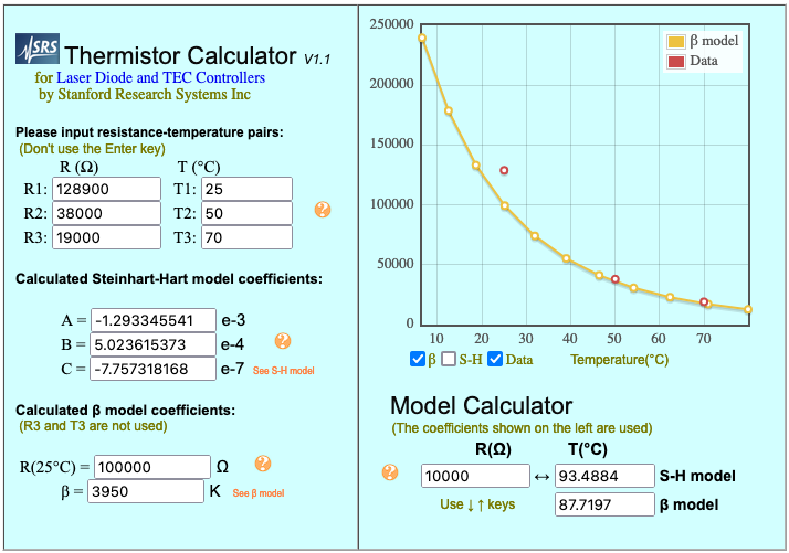
                                      54cc4bdd-34c3-4e4c-8e31-86ba7ab8e8eb-image.png

                                      Ian

                                      Bed-slinger - Mini5+ WiFi/1LC | RRP Fisher v1 - D2 WiFi | Polargraph - D2 WiFi | TronXY X5S - 6HC/Roto | CNC router - 6HC | Tractus3D T1250 - D2 Eth

                                      900turboundefined 1 Reply Last reply Reply Quote 0
                                      • 900turboundefined
                                        900turbo @droftarts
                                        last edited by

                                        @droftarts I agree with this due to the significant bed size 700x700mm using a 10mm thick sheet of Aluminium with a 5mm glass sheet on top I believe there is some lag in terms of the heating/temp reading , Am I correct in saying for R25 I just need to enter 128900?
                                        Thanks for the help !

                                        droftartsundefined 1 Reply Last reply Reply Quote 0
                                        • droftartsundefined
                                          droftarts administrators @900turbo
                                          last edited by

                                          @900turbo In the configuration tool, use the "QWG-104F-3950 (QU-BD silicone bed)" option. That gives the correct values.
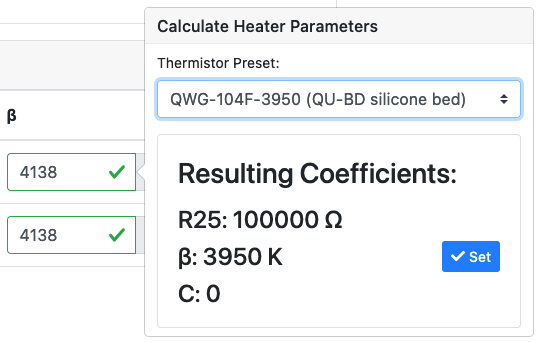
                                          f6fcb4bf-20d7-4f33-a51a-717f9c0d7994-image.png

                                          Ian

                                          Bed-slinger - Mini5+ WiFi/1LC | RRP Fisher v1 - D2 WiFi | Polargraph - D2 WiFi | TronXY X5S - 6HC/Roto | CNC router - 6HC | Tractus3D T1250 - D2 Eth

                                          1 Reply Last reply Reply Quote 0
                                          • First post
                                            Last post
                                          Unless otherwise noted, all forum content is licensed under CC-BY-SA