Using close loop Encoder for Nema 23
-
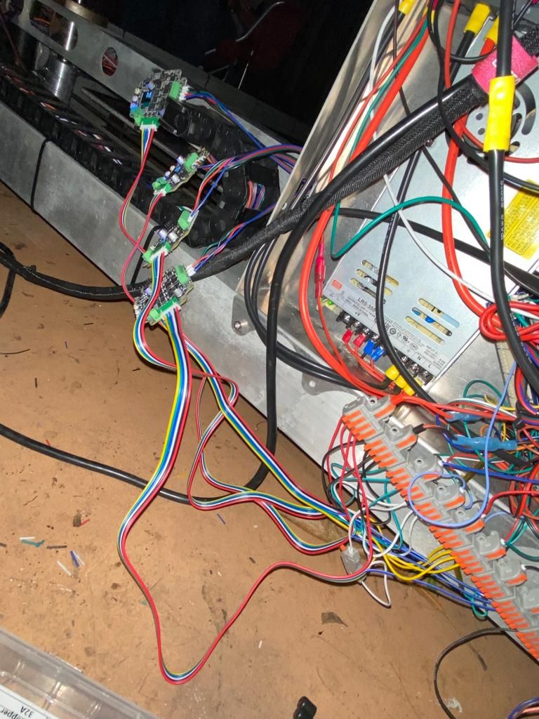
Hey Guys. I am kind of lost with this situation where I am using MKS servo 57C for my 4 Nema motor to work simultaneously and does not lose track when printing. (For this set up I am using a Break Out expansion)
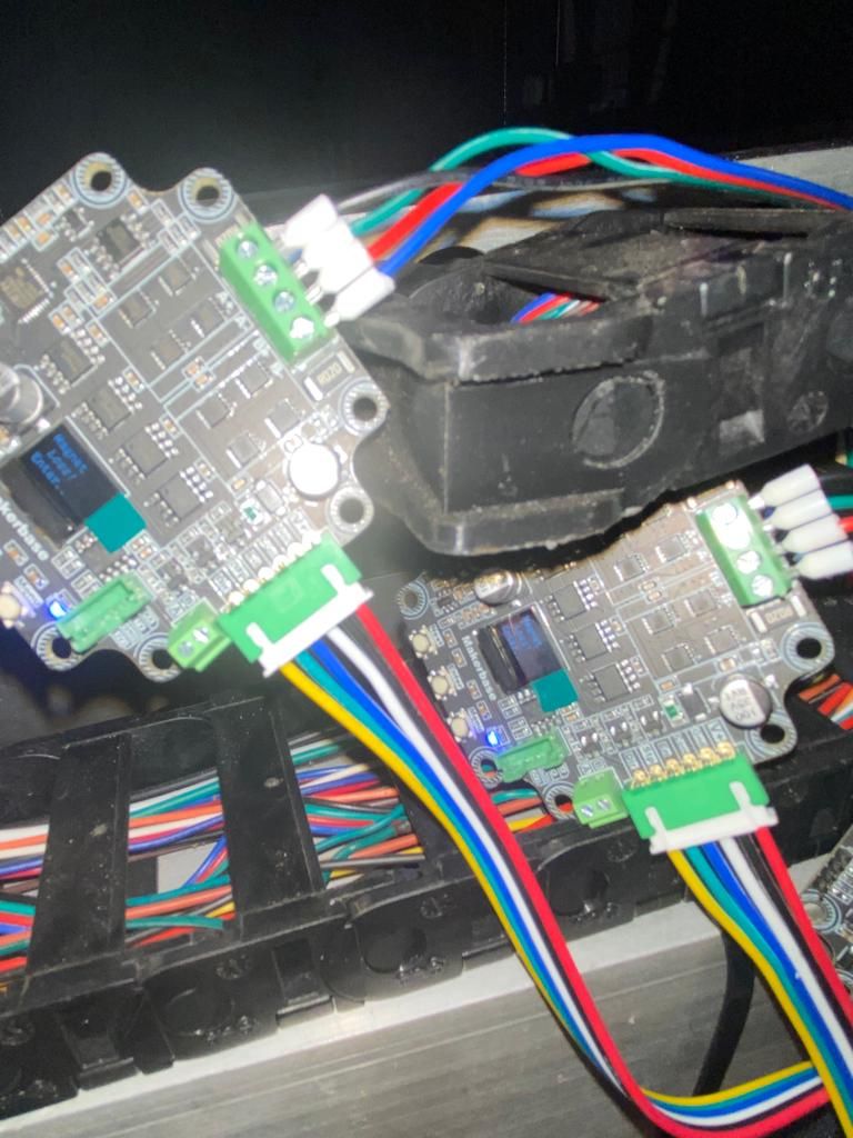
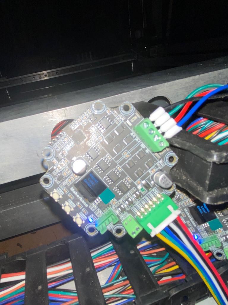
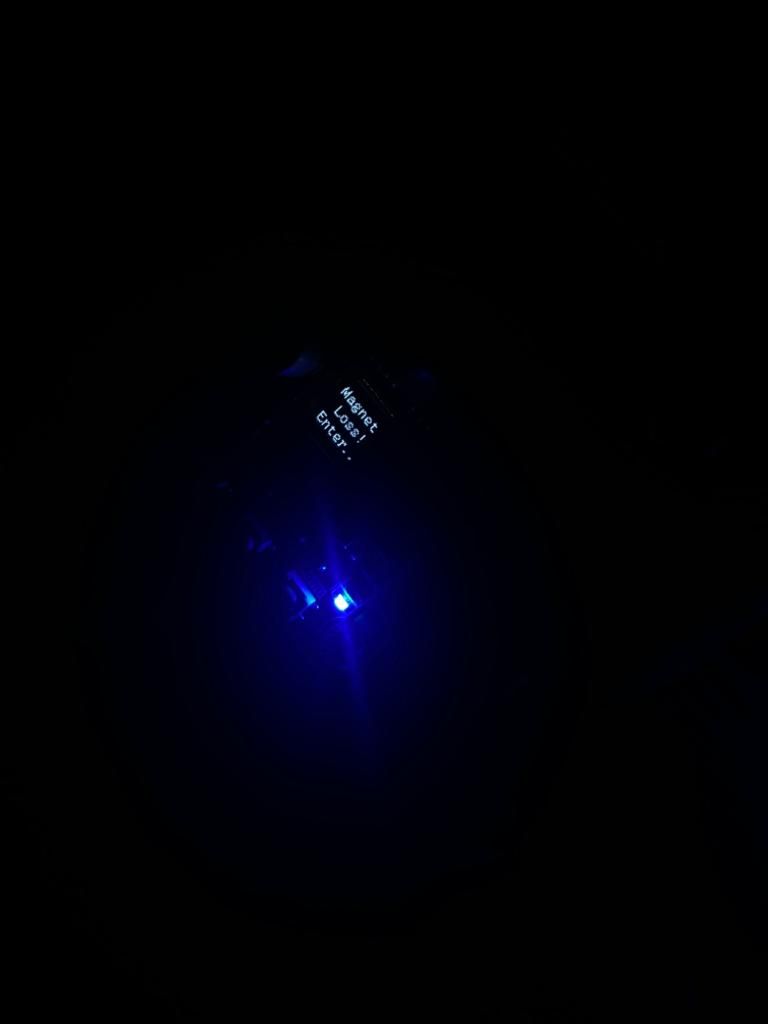
whats happening is that I am getting an error/message saying "magnet is lost" and I am not sure why is saying.
I double checked all my wring and it seems to be connected correctly and also I checked my settings for this kind of set up.
I am gonna share with you my config.g so you guys see it and can provide me with feedback.
; Configuration file for Duet WiFi (firmware version 3.3)
; executed by the firmware on start-up
;
; generated by RepRapFirmware Configuration Tool v3.3.15 on Sun Feb 19 2023 20:39:14 GMT-0500 (Eastern Standard Time); General preferences
G90 ; send absolute coordinates...
M83 ; ...but relative extruder moves
M550 P"O&MAKERSLAB" ; set printer name; Network
M552 S1 ; enable network
M586 P0 S1 ; enable HTTP
M586 P1 S0 ; disable FTP
M586 P2 S0 ; disable Telnet; Drives
M569 P5 R1 T2.5:2.5:5:5 S1 ; physical drive 5 goes forwards (X)
M569 P6 R1 T2.5:2.5:5:5 S1 ; physical drive 6 goes forwards (Y1)
M569 P7 R1 T2.5:2.5:5:5 S1 ; physical drive 7 goes forwards (Y2)
M569 P8 R1 T2.5:2.5:5:5 S1 ; physical drive 8 goes forwards (Z)M584 X6 Y7 Z5 E8 ; set drive mapping
M350 X32 Y32 Z16 E32 I1 ; configure microstepping with interpolation
M92 X21 Y21 Z400.00 E374.00 ; set steps per mm
M566 X900.00 Y900.00 Z60.00 E400.00 ; set maximum instantaneous speed changes (mm/min)
M203 X6000.00 Y6000.00 Z180.00 E3000.00 ; set maximum speeds (mm/min)
M201 X500.00 Y500.00 Z20.00 E500.00 ; set motor currents (mA) and motor idle factor in per cent
M84 S30 ; Set idle timeout; Axis Limits
M208 X0 Y0 Z-8.40 S1 ; set axis minima
M208 X1005 Y970 Z700 S0 ; set axis maxima; Endstops
M574 X1 S1 P"xstop" ; configure switch-type (e.g. microswitch) endstop for low end on X via pin xstop
M574 Y1 S1 P"ystop" ; configure switch-type (e.g. microswitch) endstop for low end on Y via pin ystop
M574 Z2 S1 P"zstop" ; configure switch-type (e.g. microswitch) endstop for high end on Z via pin zstop; Z-Probe
M558 P1 C"!zprobe.in" H5 F120 T6000 ; set Z probe type to unmodulated and the dive height + speeds
G31 P1.0 X0 Y0 Z0.14 ; set Z probe trigger value, offset and trigger height
M557 X15:1005 Y15:970 S110 ; define mesh grid; Heaters
M308 S0 P"bedtemp" Y"thermistor" T100000 B4138 ; configure sensor 0 as thermistor on pin bedtemp
M950 H0 C"bedheat" T0 ; create bed heater output on bedheat and map it to sensor 0
M307 H0 B1 S1.00 ; enable bang-bang mode for the bed heater and set PWM limit
M140 H0 ; map heated bed to heater 0
M143 H0 S300 ; set temperature limit for heater 0 to 300C
M308 S1 P"spi.cs1" Y"rtd-max31865" ; configure sensor 1 as PT1000 on pin e0temp
M950 H1 C"e0heat" T1 ; create nozzle heater output on e0heat and map it to sensor 1
M307 H1 B0 S0.50 ; disable bang-bang mode for heater and set PWM limit
M143 H1 S300 ; set temperature limit for heater 1 to 280C
M308 S2 P"spi.cs2" Y"rtd-max31865" ; configure sensor 2 as PT1000 on pin e1temp
M950 H2 C"e1heat" T2 ; create nozzle heater output on e1heat and map it to sensor 2
M307 H2 B0 S0.50 ; disable bang-bang mode for heater and set PWM limit
M143 H2 S315 ; set temperature limit for heater 2 to 315C; Fans
M950 F0 C"fan0" Q500 ; create fan 0 on pin fan0 and set its frequency
M106 P0 S0 H-1 ; set fan 0 value. Thermostatic control is turned off
M950 F1 C"fan1" Q500 ; create fan 1 on pin fan1 and set its frequency
M106 P1 S1 H1:2 T45 ; set fan 1 value. Thermostatic control is turned on; Tools
M563 P0 D0 H1:2 S"Typhoon" ; define tool 0
G10 P0 X0 Y0 Z0 ; set tool 0 axis offsets
G10 P0 R0 S0 ; set initial tool 0 active and standby temperatures to 0C; Custom settings are not defined
M575 P1 B57600 S1
T0Pictures of the encoder:


-
@JlunaMX It looks, like you have to mount the boards on the back of the stepper and put a small magnet on the rear end of the motor-shaft?
If the distance to the magnet is too big or is missing, you will get this error message. -
@JlunaMX Yes, you need to attach a magnet to the stepper motor and mount the boards on the back of the stepper motors with the correct spacing.
THIS DOCUMENT talks about how to attach the magnet to the back of the stepper motor.
-
@alankilian thank you guys it worked!!!
-
@o_lampe It worked out!! thank you!!
-
 undefined dc42 marked this topic as a question
-
 undefined dc42 has marked this topic as solved
-
 undefined droftarts referenced this topic