5 bar scara on duet3!
-
@michaelr123 said in 5 bar scara on duet3!:
What kind of robot are you building? I'd be interested to see what you're working on.
I started about three years ago with 5-bar-scara and developed the kinematics for it for RRF. Since then I'm developing robot kinematics, which includes all sorts of combinations of rotary and linear axes. So I'm building 6 axis industrial robots, but also CNC 5 axis and Cartesian ones. With extensions, the robot kinematics can support parallel kinematics also, like 5-bar-scara, CoreXY 5 axis and tripteron.
The project thread is https://forum.duet3d.com/topic/17421/robotic-kinematics/330?_=1670950282842 and https://forum.duet3d.com/topic/30228/robot-prototypes-robot-kinematics (but there are other pages about prototypes, because I made several tries) and documentation at https://docs.duet3d.com/User_manual/Machine_configuration/Configuring_RepRapFirmware_for_a_Robot_printer with multiple linked pages.
I've started with what I read about robots, the Siciliano book, based on Denavit-Hartenberg, but discovered a half year ago that screw theory is superior. Then I detected geometric algebra as method to solve some unsolved problems, and this is the status today. I rewrite the kinematics to the new methods and start prototyping after it.
An open question is Stewart-Gough. I'm not sure whether I can manage to develop it. And one interesting topic is to support compliant hinges. (I mean e. g. the book Howell Handbook of Compliant Mechanisms).
-
I stand on the shoulder of giants then! Thank you for the hardwork on that. I took a robotics class in college and at one point was really good at inverse kinematics. I’m not sure I could figure out the pages of differential equations at this point

The peak of my own work in this space was a matlab script that could convert XYZ gcode from slic3r to RR-theta for a parallelogram robotic arm I used for a robotic painter in an art competition in college. As long as you keep things determinant its all good. As soon as you add additional degrees of freedom you need to start adding additional algorithms to sort through infinite solution spaces. 6 axis is just infinity cubed the problems!
-
@michaelr123 Paden-Kahan divided the inverse kinematics problem into parts of solving one or two angles each, getting all 8 solutions for industrial robots. There are combinations of unsolved configurations, which I want to solve with the help of geometric algebra. Geometric algebra is great, but difficult to manage. One problem is that some development is too new to be standardized, the authors use different syntax and methods. I try to document what I understood...
I like parallel kinematics like 5-bar-scara, so it is sure that I'll implement it into robot kinematics. If you want, you can test it when I have a build.
-
@JoergS5 I don't understand half of the math-talk here, but it reminds me of the NASA-movie "Hidden Figures" where they used 17th century math in the end (Euler angles).
-
@o_lampe I love mathematics since ever, but nothing of all the topics I learn today was tought in school... Geometric algebra is from 19 th century, not so far away from your Euler angles.
I BTW used Euler angles at the beginning for robot kinematics, but it has some serious restrictions, the main one the gimbal lock, which means that some movements cannot be made, especially experienced in aviation.
-
Hello again!
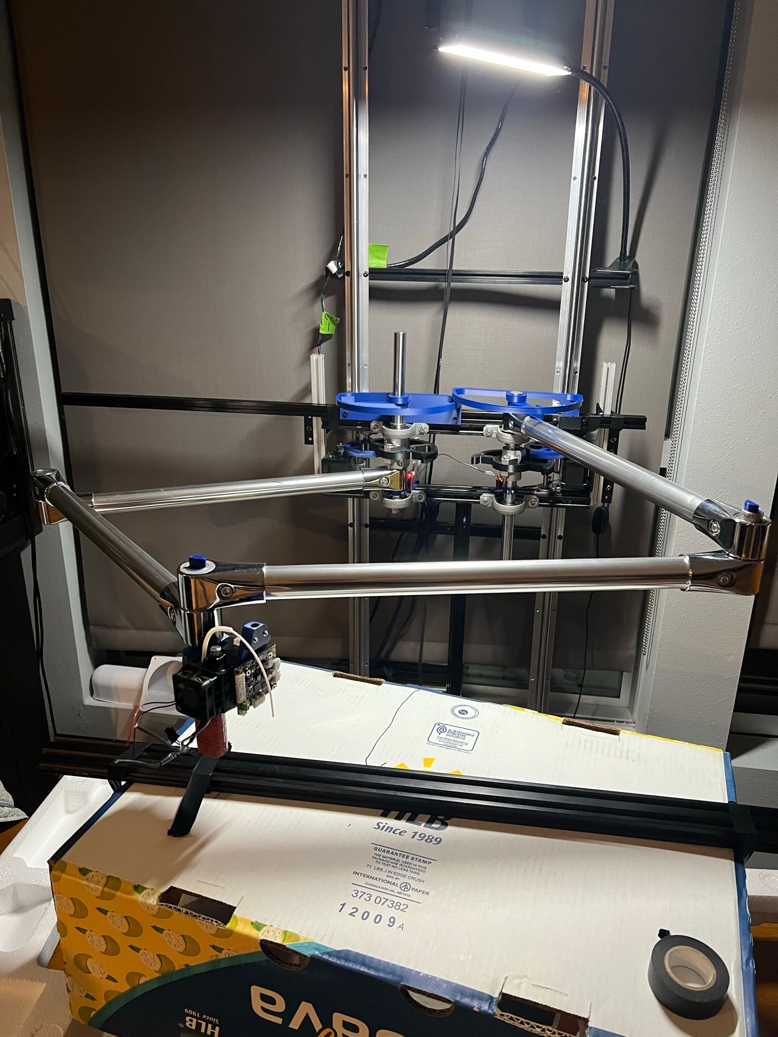
I've got some time tomorrow to work on this again, any good recommendations for calibrating a 5 bar scara for dimensions? I got endstops in place and everything is spinning the right direction again so now I'm trying to ensure that my M669 code is correct. from some initial measurements I'm not quite there in terms of lining up the hotend with where the system says it should be.
One thing that might be nice to know is the angle or rotation the system thinks each arm is at. It would be good to have that piece of info to sort out where the discrepancy may come from.
-
@michaelr123 said in 5 bar scara on duet3!:
angle or rotation the system thinks each arm is at
good morning,
the only hint I can give for calibration is my experience from my own 5 bar prototype, where I had some tools to measure the angles. But three years ago I didn't log my own blog addresses, so you must search in the threads *). You can also check how bondus calibrated his printer (on hackatlon, youtube).
https://reprap.org/forum/read.php?185,490216,page=1 may give valuable information also.*) here is it: https://forum.duet3d.com/topic/14996/five-bar-parallel-scara-prototypes/10
In robot kinematics, the angles are easy to report, but in this kinematics this information is not prepared. Your next question: this will take a few weeks, until I have the code.
In general, the calculation goes like knowing the coordinates and then vector based calculation is easy:
from the cross product (or in geometric algebra the wedge/outer product) gives the sin of the angle, and the dot (=inner) product gives the cos of the angle, and together you can take the atan2 of the angle, with correct 360 degree values. The angle you search is then the angle between the vectors of the distal arm and the x axis.
The point between proximal and distal arm is calculated in the method of circle intersection in the kinematics.
-
@o_lampe said in 5 bar scara on duet3!:
@JoergS5
I thought of something different:
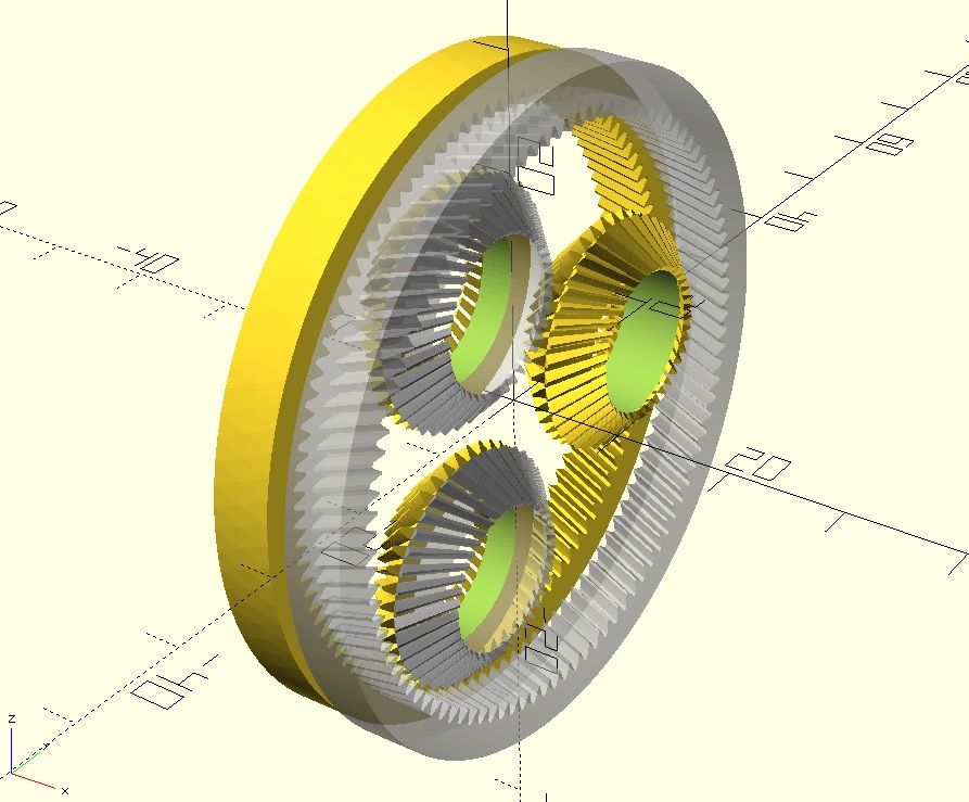
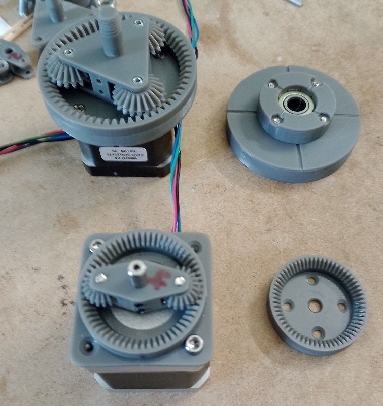
instead of using a belt to connect the involute gears, use dual beveled gears which can rotate freely on a concentric rotor.
That way the fixed side and the output side can have different module and teeth count. (They don't have to share the pitch of the belt)I tried to make a quick sketch, but couldn't draw a beveled involute gear.

[OT]
I don't want to hijack this thread, but since the discussion went back and forth about harmonic drives and me sharing my idea of using beveled gears instead of belt; I thought it is only fair to introduce my design here.
I will start a new thread with more details as soon as I have a fully working showcase.
So far I can tell, that due to the beveled gears backlash can be eliminated.
Also there is no vibration from eliptic rotors and the design doesn't require special parts like a flexspline and those unique ballbearings.The big one is a bit overkill and has 21:1 ratio. The small one has 31:1 and is the smallest printable version I'd dare to use.

-
@o_lampe that's interesting, and the more options we have, the better!
How about the idea to standardize the outer dimensions/axes/meachnical connectors etc for use as community, so we can exchange it module-like (similar to Nema standards)?
-
@JoergS5 Good idea, I've made the output gear to fit on an mgn12-rail or 2040 extrusion with a 20x20mm M3 pattern. (can be M5 too)
My design is made on openscad and I try to use parameters were possible. Easy to make changes and the resin printer spits the parts out in no time
I also made a NEMA17 bracket (*) with the same hole pattern, but i think that it already exists on thingiverse...//edit *) the shaft-height above ground will be important, too.
-
@o_lampe let's talk about modules in a few weeks/months again, I'll use extrusion measures and stepper boring hole distances as well until then.
Stepper distance of 31 made me unhappy in the past. -
@JoergS5 I also thought of adapting the gearbox to 380 or 540/600 sized dc brushed motors. But that's a subject for a new thread.
-
looks good mate!
I'm currently working on calibration and while I think I'm closing in on getting a straight 600mm line X axis at Y600, I'm noticing there's still way to much wobble and inconsistency to use this as a printer.

I think my two options are to switch to this harmonic drive stepper motor (aliexpress link is $54 rather than $155 from amazon in the US):
I could either directly drive the 20mm shafts from the motor or try a 2:1 gear reduction. Either way, there's a lot less shafts and plastic gears in between the stepper and the output to add backlash and spring to the system.
otherwise I might try building a T-shaped core-XY first to see how that performs in comparison. Something with a long X axis and a shorter Y axis. I have some big printed projects I want to get moving for the summer so at this point I just want a motion system that can get the job done. I think there's a longer leadtime option for those motors that saves a bunch on shipping that I can order and have in a month or so.
-
@michaelr123 in my opinion you're simply using too long arms. Long arms multiply the errors. If you're using 10 cm arms, you'll get much better solution. You can use cantileved mode to place the hotend a bit away from the last hinge. Placing the XY actuator with bigger distance will also help (but this conflicts with the short arms). I have/had similar problems with 6 axis robot, so this is from my experience (better would be parallel arms vertically or parallelogram structure. Stability could be gained by overconstraining with tensegrity methods also).
But if your project requirement is a big print area and you have time pressure, using CoreXY (or Cartesian in Gantry style) will probably be a better option.