bowden drive to direct drive set up, but how do I configure it?
-
@jens55 thanks for your advice.
Yeah what you said is bang on. I think having some slippage on the Bowden extruders is a good thing---like you said, impossible to calibrate them 100% equal and over longs prints the difference will add up, and something has to give.
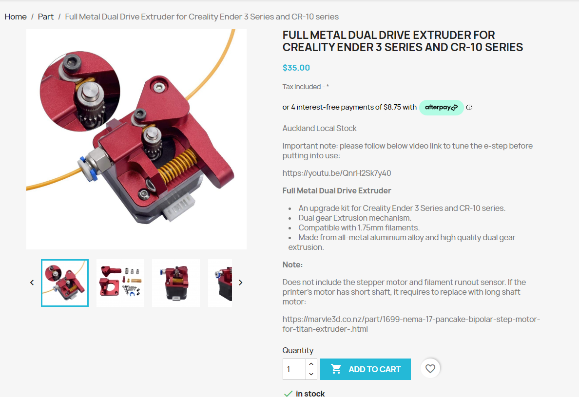
I was planning on splashing out to buy 3 x orbiter 2.0 extruders, in light of your advice I think I will stick with the current CW2 extruder as the main directive drive extruder, then use something cheap like this for the Bowden extruders.
what do you think?
-
@Gordon-Lin, that extruder is exactly what I was thinking about. Please note that I have not tried any of this so I might be totally wrong!
-
@Gordon-Lin Push-pull arrangements are tricky to do for the reasons that have been pointed out. "Built-in slippage" is one approach that could work. Another is to calibrate the "push" extruder so that it always pushes very slightly more than the "pull" extruder. That way, there will always be some slack in the filament between the two. Of course, over a very long print, this slack will form a loop which will need to be accommodated somehow. You'd need to do the maths but let's say you use 100 metres of filament between colour changes. If the push extruder was calibrated to give 0.1 % more than the pull extruder, then you'd end up with a loop of 0.1 metres or 100mm (about 4 inches in old money), which shouldn't be too difficult to accommodate. IIRC, a full 1Kg spool is about 300 metres (depending on filament) so even that would only make a loop of about 300mm or about a foot in old money.
-
Another approach is to have sensor in the filament between the two extruders. It could be a simple micro switch that gets triggered when the filament is taut and not triggered when it is slack. You set the switch up as a trigger and run a macro that feeds (say) 100mm of filament from the "push" extruder whenever that trigger occurs.
-
I keep picturing computer tape drives that old main frame computers used. These used a system just like that. There was a loop of tape and if the loop got too small, more tape would be fed into that 'buffer' loop.
I would hate to be the person trying to come up with all the macros required for feeding filament or retracting filament and all the edge cases that might occur. My brain is hurts just thinking about it .... Still, that would be the 'proper' way of doing it rather than the much simpler slippage system. -
In my day job I sell high end welding equipment, some of which has two or more feed motors.
In some cases the torch motor also changes direction, much like retraction, but at a much higher frequency.
They way it is handled is to have a "boomerang" shaped buffer between the main motor and the torch motor.
Inside is a section of ptfe tube attached to a pivoting arm.
So as @deckingman has suggested, if the front motor retracts the tube will "bulge" out and the speed of the rear motor is reduced or stopped.
If the rear motor lags, it hits a limit and either speeds up the main motor or stops and alarms.
The torch motor is a servo and the main motor is a DC unit, so they don't bother trying to get fully coordinated movements.
One could probably also use a potentiometer with an arm.
You could monitor the value in daemon.g and adjust the steps per mm based on its position. -
@jens55 said in bowden drive to direct drive set up, but how do I configure it?:
.....................I would hate to be the person trying to come up with all the macros required for feeding filament or retracting filament and all the edge cases that might occur. .....................
There isn't all that much to worry about. If you use firmware retraction (G10/G11), any and all extruders that are associated with a tool get retracted and un-retracted simultaneously. That's how it works with a multi-input hot end because retracting one filament simply pulls filament from one or more of the unused inputs rather than the nozzle tip. So if the OP uses firmware retraction on his push-pull setup, he doesn't have to worry.
EDIT. This is just like using a mixing hot end - the only difference is that one must ensure that the sum of the mixing ratios adds up to one (or 100% if you prefer) whereas in a push-pull arrangement, both extruders must be set to 1 or 100%.
-
@jens55 all good, I understand the nature of all this, nothing is guaranteed---I proceed at ma own risk
")
-
@deckingman wow, the math really puts it in perspective how little bit of difference really adds up
yeah, imma dial back the tension of the push extruders so they can push filament down but would slip if encountered "too much" resistance. How much is too much is yet to be determined.
I just thought of another way--------instead of using mechanical slippage by dialing back extruder pinch tension, we keep the pinch tension as normal, but artificially limit the extruder motor current to deliberately let the motor skip steps when necessary, like a "electrical slippage" to "take up the slack".
I assume deliberately making the extruder skipping steps won't harm the motor drivers? @dc42 any input/thoughts on this? Thank you for your time
-
@OwenD thanks for your input. that welding system is smart and interesting, quite logical if you ask me.
I am not Gcode wizard so I think I will stick with what I know best which is mechanical design----so I will keep it simple at first, build in slippage on the push extruder it is

-
guys, thank you for your input, I truly appreciate it.
I have ordered the extruders and will pick them up this avo...I will start experimenting / testing when I can (in a day or so) and will keep updating this thread to keep you guys in the loop

-
@deckingman @Exerqtor @jens55 @OwenD I got it roughly configured and working----3 stepper motors on the bench and if I select T0, D0+D1 spins, if I select T1, D0+D2 spins. Thanks again for your help
the next part is to add icing on the cake, and this will be a filament Y splitter, with microswitch on all 3 paths + a bit of (maybe a lot of) conditional G code to make this idiot proof

I have attached my config.g here, hopefully this can serve as a starting point for someone
-
@Gordon-Lin, glad you got it going! BTW, no such thing as idiot proof
-
@Gordon-Lin
did you get it up and running with the micro switch in the splitter?