Duet3D Logo Duet3D
    • Tags
    • Documentation
    • Order
    • Register
    • Login

    Problems with input shaping

    Scheduled Pinned Locked Moved
    Tuning and tweaking
    5
    47
    2.7k
    Loading More Posts
    • Oldest to Newest
    • Newest to Oldest
    • Most Votes
    Reply
    • Reply as topic
    Log in to reply
    This topic has been deleted. Only users with topic management privileges can see it.
    • Leeundefined
      Lee @jay_s_uk
      last edited by

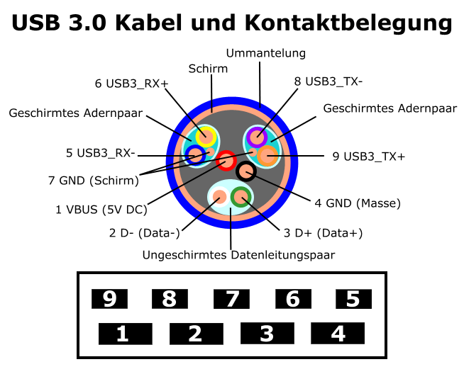
      @jay_s_uk Its a Flat Ribbon cabel
      IMG_2416.JPG

      1 Reply Last reply Reply Quote 0
      • Leeundefined
        Lee @jay_s_uk
        last edited by

        @jay_s_uk
        when i cut up a usb cabel do i need to connet the shiling to groung?

        jay_s_ukundefined 1 Reply Last reply Reply Quote 0
        • jay_s_ukundefined
          jay_s_uk @Lee
          last edited by

          @Lee yes, connect the shielding to ground. This is the suggested wiring
          7b82e5e4-92d1-4657-a55c-4f00a1899bec-image.png

          Owns various duet boards and is the main wiki maintainer for the Teamgloomy LPC/STM32 port of RRF. Assume I'm running whatever the latest beta/stable build is

          Leeundefined 1 Reply Last reply Reply Quote 1
          • Leeundefined
            Lee @jay_s_uk
            last edited by Lee

            @jay_s_uk I Have made a new cable from a USB 3 cable but the problem persists is there any way to test if the accelerometer responds to the board

            jay_s_ukundefined tasundefined 2 Replies Last reply Reply Quote 0
            • jay_s_ukundefined
              jay_s_uk @Lee
              last edited by

              @Lee the only way really is to try and collect data. You can check what M955 P0 outputs too

              Owns various duet boards and is the main wiki maintainer for the Teamgloomy LPC/STM32 port of RRF. Assume I'm running whatever the latest beta/stable build is

              1 Reply Last reply Reply Quote 0
              • tasundefined
                tas @Lee
                last edited by

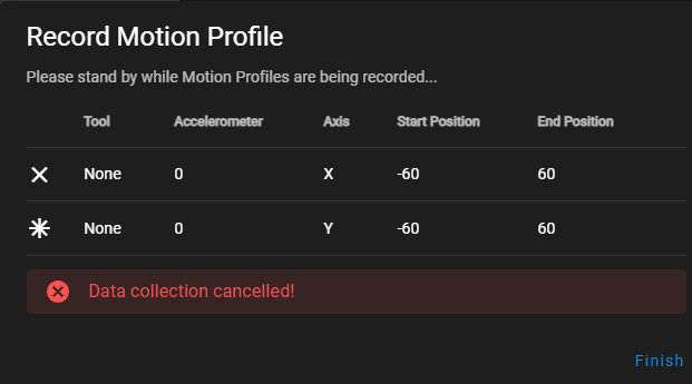
                @Lee I have the same issue. It says 'data collection cancelled' after the first move and the Y move does not happen but if you return to the analysis tab and click the refresh arrow the latest data should appear. It will only be for the X axis move though.

                To do the Y axis do that move seperately.

                Leeundefined 1 Reply Last reply Reply Quote 0
                • Leeundefined
                  Lee @tas
                  last edited by

                  @JAY_S_UK @tas I did what to recommended and came measured these values. And have set the target frequency to the ighest peak. but it dont notice any difference in ringing/ghosting. Am i doing something wrong?

                  9a34aca9-a739-48fa-965c-92bf1ba4d7a6-image.png

                  jay_s_ukundefined tasundefined 2 Replies Last reply Reply Quote 0
                  • jay_s_ukundefined
                    jay_s_uk @Lee
                    last edited by

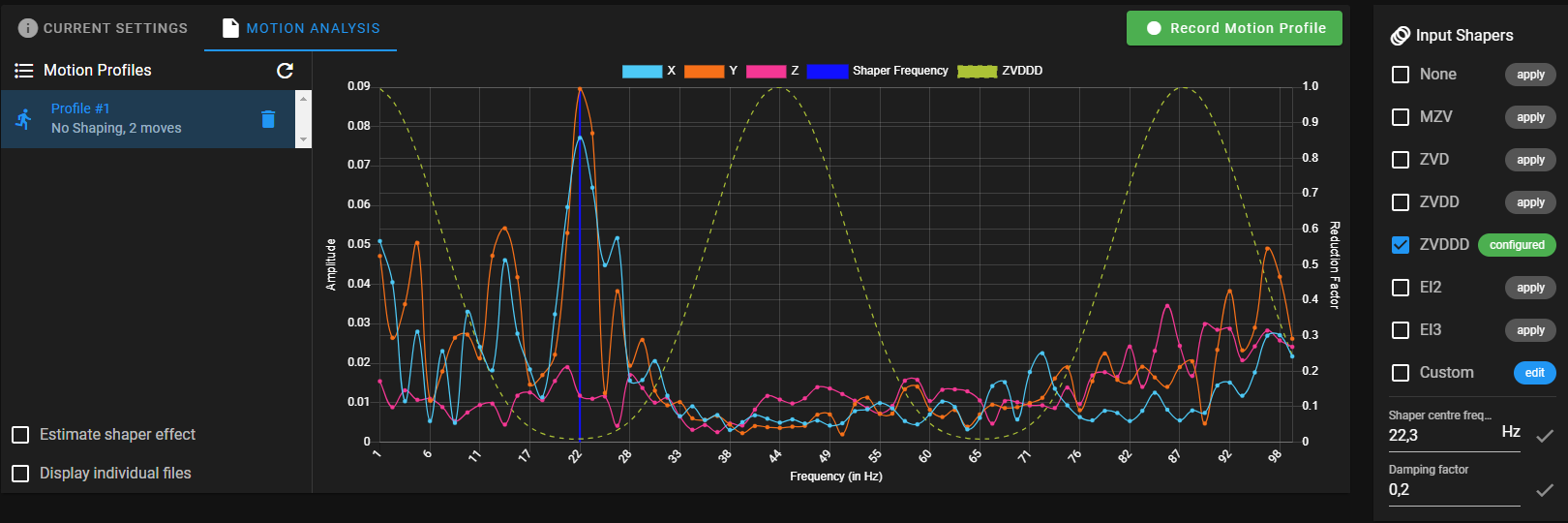
                    @Lee 22Hz seems quite low. Can you post a photo of the ringing you're seeing?

                    Owns various duet boards and is the main wiki maintainer for the Teamgloomy LPC/STM32 port of RRF. Assume I'm running whatever the latest beta/stable build is

                    Leeundefined 1 Reply Last reply Reply Quote 0
                    • Leeundefined
                      Lee @jay_s_uk
                      last edited by

                      @jay_s_uk b49e3eb0-af0f-4316-9425-9c5dc1915dd4-image.jpeg

                      droftartsundefined 1 Reply Last reply Reply Quote 0
                      • tasundefined
                        tas @Lee
                        last edited by

                        @jay_s_uk beat me to it. 22Hz does seem low. From your earlier photo it looks like you are using a Delta printer. All of mine are cartesian so I hope my information is applicable. My printers are in the 38 to 45 Hz range. Others on the forum with Deltas are in the 50Hz range. Check your accelerometer is mounted securely.

                        You should be able to run the input shaping plugin then set a center frequency as you have done. You should then be able to pick an input shaper at the right and do another run to see the effect. I haven't done that last step lately. Instead I just set the frequency in my config and run a test print because there can be undesireable effects from some input shaping settings.

                        If you have Pressure Advance enabled turn that off. You will have to recheck PA again after you have selected your ideal Input Shaper and frequency/damping.

                        Instead of 0.2 Damping Factor try 0.1 or 0.

                        I am not sure a benchy is the best test for Input Shaping. Try the Klipper ringing_tower.stl in vase mode. Many other issues can affect a Benchy. The Ringing_Tower makes the Input Shaping changes very visible. Edit your gcode to change input shapers every 5mm or so then decide which one you are happiest with.

                        I hope these suggestions are valid for your printer.

                        1 Reply Last reply Reply Quote 2
                        • droftartsundefined
                          droftarts administrators @Lee
                          last edited by

                          @Lee it looks like your M566 (max instantaneous speed change, or jerk) line has had M201 (max acceleration) put at the beginning of it, and/or has been pulled back into the comment for that line. There's another M201 a couple of lines further down, so I assume this is an error:

                          M201 X600.00 Y600.00 Z600.00 E600.00                    ; set maximum instantaneous speed changes (mm/min) M566 X1200.00 Y1200.00 Z1200.00 E1200.00
                          M203 X70000 Y70000 Z70000 E7200.00                  	; set maximum speeds (mm/min)
                          M201 X7500 Y7500 Z3000 E3000                            ; set accelerations (mm/s^2)
                          

                          There's a couple of notes in the M593 entry in the Gcode dictionary that might be relevant:

                          High X and Y jerk values reduce the effectiveness of DAA; therefore you should set the X and Y jerk limits only as high as necessary to allow curves to be printed smoothly.

                          Keep in mind that you have to retune Pressure Advance after you have configured Input Shaping. The Pressure Advance will differ from shaper to shaper and from frequency to frequency.

                          So I'm not sure what M566 is actually set at the moment, but as you're seeing ringing at particularly low frequency, the chances are a high jerk is exciting this at the moment. You could probably reduce M566 to X300 Y300, or perhaps even lower. Check curves print smoothly, though.

                          Ian

                          Bed-slinger - Mini5+ WiFi/1LC | RRP Fisher v1 - D2 WiFi | Polargraph - D2 WiFi | TronXY X5S - 6HC/Roto | CNC router - 6HC | Tractus3D T1250 - D2 Eth

                          Leeundefined 1 Reply Last reply Reply Quote 0
                          • Leeundefined
                            Lee @droftarts
                            last edited by Lee

                            @droftarts I have change my config and lowerd jerk i have tried 150 and 300

                            but i still get the Data collection cancelled! error.
                            e2c5342e-a3c0-496c-bb72-5b7daee0c81e-image.png

                            Is it possible that the I parameter may be wrong i have a LIS3DSH mounted to the back of my tool head like this .
                            IMG_2431.JPG

                            this is my config now:

                            ; Configuration file for Duet Maestro (firmware version 3.3)
                            ; executed by the firmware on start-up
                            ;
                            ; generated by RepRapFirmware Configuration Tool v3.3.15 on Sun Mar 12 2023 20:43:39 GMT+0100 (Mitteleuropäische Normalzeit)
                            
                            ; General preferences
                            G90                                                     ; send absolute coordinates...
                            M83                                                     ; ...but relative extruder moves
                            M550 P"Kossel XL"                                       ; set printer name
                            M665 L371.000:371.000:371.000 R168.486 H346.526 B120.0  ; Set delta radius, diagonal rod length, printable radius and homed height B116
                            M666 X0 Y0 Z0                                           ; put your endstop adjustments here, or let auto calibration find them
                            M918 P1 E4 F2000000               ; configure direct-connect display
                            
                            ; Network
                            M552 P0.0.0.0 S1                                        ; enable network and acquire dynamic address via DHCP
                            M586 P0 S1                                              ; enable HTTP
                            M586 P1 S1                                              ; enable FTP
                            M586 P2 S1                                              ; enable Telnet
                            
                            ; Drives
                            M569 P0 S1   	                                        ; physical drive 0 goes forwards
                            M569 P1 S1                                              ; physical drive 1 goes forwards
                            M569 P2 S1                                              ; physical drive 2 goes forwards
                            M569 P3 S0 D3                                           ; physical drive 3 goes forwards
                            M584 X0 Y1 Z2 E3                                        ; set drive mapping
                            M350 X16 Y16 Z16 I1                                     ; configure microstepping with interpolation
                            M350 E16 I0                                             ; configure microstepping without interpolation
                            M92 X160 Y160 Z160 E663.00                                 ; set steps per mm
                            M566 X300.00 Y300.00 Z300.00 E600.00                    ; set maximum instantaneous speed changes (mm/min)
                            M203 X30000 Y30000 Z30000 E7200.00                  	; set maximum speeds (mm/min)
                            M201 X5000 Y5000 Z3000 E3000                            ; set accelerations (mm/s^2)
                            M906 X600 Y600 Z600 ;I100                             	; set motor currents (mA) and motor idle factor in per cent
                            M906 E1000 ;I10                                          ; set motor currents (mA) and motor idle factor in per cent
                            ;M84 S5                                                  ; Set idle timeout
                            M950 S0 C"servo"                                        ; configure servo
                            
                            ; Axis Limits
                            M208 Z0 S1                                              ; set minimum Z
                            
                            ; Endstops
                            M574 X2 S1 P"!^xstop"                                   ; configure switch-type (e.g. microswitch) endstop for high end on X via pin !^xstop
                            M574 Y2 S1 P"!^ystop"                                  	; configure switch-type (e.g. microswitch) endstop for high end on Y via pin !^ystop
                            M574 Z2 S1 P"!^zstop"                                  	; configure switch-type (e.g. microswitch) endstop for high end on Z via pin !^zstop
                            
                            ; Z-Probe
                            M558 P8 R1 C"zprobe.in" H2 F300 T1500 ;S0.01 A15	    ; set Z probe type to effector and the dive height + speeds M558 P5 R0.4 C"zprobe.in" H2.5 F240 T1500 M558 P5 R0.75 C"zprobe.in" H5 F60 T4800	
                            ;M558 H30                                               ;*** Remove this line after delta calibration has been done and new delta parameters have been saved
                            G31 P1 X0 Y0 Z-0.2											; set Z probe trigger value, offset and trigger height
                            M557 R110 S30                                          	; define mesh grid
                            
                            ; Heaters
                            M308 S0 P"bedtemp" Y"thermistor" T100000 B4092          ; configure sensor 0 as thermistor on pin bedtemp
                            M950 H0 C"bedheat" T0                                   ; create bed heater output on bedheat and map it to sensor 0
                            M307 H0 B0 S1.00                                        ; disable bang-bang mode for the bed heater and set PWM limit
                            M140 H0                                                 ; map heated bed to heater 0
                            M143 H0 S100                                            ; set temperature limit for heater 0 to 100C
                            M308 S1 P"e0temp" Y"thermistor" T100000 B4725 C7.06e-8  ; configure sensor 1 as thermistor on pin e0temp
                            M950 H1 C"e0heat" T1                                    ; create nozzle heater output on e0heat and map it to sensor 1
                            M307 H1 B0 S1.00                                        ; disable bang-bang mode for heater  and set PWM limit
                            M143 H1 S280                                            ; set temperature limit for heater 1 to 280C
                            
                            ; Fans
                            M950 F0 C"fan0" Q500                                    ; create fan 0 on pin fan0 and set its frequency
                            M106 P0 C"Part cooling Fan" S0 H-1                      ; set fan 0 name and value. Thermostatic control is turned off
                            M950 F1 C"fan1" Q500                                    ; create fan 1 on pin fan1 and set its frequency
                            M106 P1 C"Hotend Fan" S1 H1 T45                         ; set fan 1 name and value. Thermostatic control is turned on
                            
                            ; Tools
                            M563 P0 S"E3D V6" D0 H1 F0                              ; define tool 0
                            G10 P0 X0 Y0 Z0                                         ; set tool 0 axis offsets
                            G10 P0 R0 S0                                            ; set initial tool 0 active and standby temperatures to 0C
                            
                            ; Custom settings
                            M81 C"pson"                                             ; PSU off
                            M955 P0 C"twd0+twck0" I16 P10                           ; Accelorometer
                            M107                                                    ; fans off
                            
                            M572 D0 S0.0175                                         ; S0.3 ;S0.15 ; Set Pressure advance (old 0.95) 0.05
                            ;M592 D0 A0.0124929539412195 B0.00208450767751017 L0.2  ; Configure nonlinear extrusion
                            M579 X1.0195758564437194127243066884176 Y1.0141987829614604462474645030426 Z1 											; Scale Cartesian axes
                            
                            ; Input shaping
                            ;M593 P"ZVDDD" F0 S0
                            
                            ;Triggers
                            
                            ;M950 J1 C"!^exp.pa21"
                            ;M581 P1 S0 T2 R2
                            
                            ;Orbiter Filament Sensor
                            M950 J2 C"!e0_stop"                                     ; define logical input for filament auto load
                            M581 P2 T3 S0 R0                                        ; define trigger for filament auto load triggers trigger3.g
                            
                            ;M950 J3 C"!exp.pa22"                                    ; define logical input for filament unload
                            ;M581 P3 T4 S0 R0                                        ; define trigger for filament auto load triggers trigger4.g
                            
                            M591 D0 P2 C"!^e1_stop" S1							   	; filament monitor connected to E1_stop
                            
                            ; Miscellaneous
                            M501                                                    ; load saved parameters from non-volatile memory
                            T0                                                      ; select first tool
                            
                            droftartsundefined tasundefined 2 Replies Last reply Reply Quote 0
                            • droftartsundefined
                              droftarts administrators @Lee
                              last edited by

                              @Lee said in Problems with input shaping:

                              M955 P0 C"twd0+twck0" I16 P10 ; Accelorometer

                              You have P0 and P10 in the same line. Did you mean R10?
                              Having the I parameter wrong wouldn't stop data collection.

                              Ian

                              Bed-slinger - Mini5+ WiFi/1LC | RRP Fisher v1 - D2 WiFi | Polargraph - D2 WiFi | TronXY X5S - 6HC/Roto | CNC router - 6HC | Tractus3D T1250 - D2 Eth

                              Leeundefined 1 Reply Last reply Reply Quote 0
                              • Leeundefined
                                Lee @droftarts
                                last edited by

                                @droftarts Your right i change it to R10 but i still get "Data collection cancelled!" When run the recording right after finnishing the first move.

                                droftartsundefined 1 Reply Last reply Reply Quote 0
                                • droftartsundefined
                                  droftarts administrators @Lee
                                  last edited by

                                  @Lee Hmm. Can you post a picture of your wiring at the Duet end? Can you check the wiring continuity? Does the fan (with the fan wire very close to the accelerometer wiring) run when you're collecting data? Anything else that might be causing interference?

                                  Ian

                                  Bed-slinger - Mini5+ WiFi/1LC | RRP Fisher v1 - D2 WiFi | Polargraph - D2 WiFi | TronXY X5S - 6HC/Roto | CNC router - 6HC | Tractus3D T1250 - D2 Eth

                                  Leeundefined 1 Reply Last reply Reply Quote 0
                                  • tasundefined
                                    tas @Lee
                                    last edited by

                                    @Lee The 'Data Collection Cancelled' problem was solved by @chrishamm. Refer to this post by @alexjx

                                    https://forum.duet3d.com/topic/32762/3-5b4-input-shaping-plugin-bug-data-collection-cancelled/13?_=1687311263398

                                    Go down to the google drive link provided and get the latest version of DWC.

                                    It is very important to get the axes correct with the I parameter but I have no idea how to do that for a delta printer. This link should help you get the orientation right (I think they use the same board as you):
                                    https://forum.duet3d.com/topic/31411/lis3dsh-orientation-on-a-delta-printer/6

                                    Leeundefined 1 Reply Last reply Reply Quote 0
                                    • Leeundefined
                                      Lee @droftarts
                                      last edited by Lee

                                      @droftarts Here are pictures of the cabel it selfe i have connected the shielding oh the wire to ground (underneath The shrink tubing)
                                      continuity is good aswell

                                      1 Reply Last reply Reply Quote 0
                                      • Leeundefined
                                        Lee @tas
                                        last edited by Lee

                                        @tas https://forum.duet3d.com/topic/31411/lis3dsh-orientation-on-a-delta-printer/6
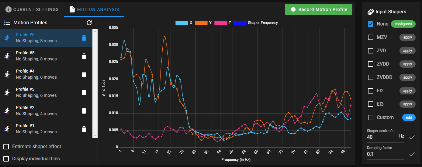
                                        I have checked I16 seems to be right for me.

                                        I have installed the the version you suggested i am was able to finish the data collection.

                                        here are the results: (using M566 X150.00 Y150.00 Z150.00)
                                        d4bc100c-4c85-45f4-8d7a-689c7318823e-image.png

                                        tasundefined droftartsundefined 2 Replies Last reply Reply Quote 0
                                        • tasundefined
                                          tas @Lee
                                          last edited by

                                          @Lee It's good the data collection is working properly now so your cable is likely ok. Your frequency is still around 20Hz though. I think you need a delta expert to help and that is not definitely not me. Perhaps @dc42 could take a look for you.

                                          Leeundefined 1 Reply Last reply Reply Quote 0
                                          • Leeundefined
                                            Lee @tas
                                            last edited by

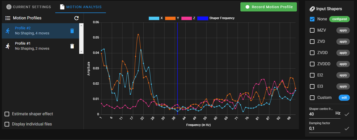
                                            @tas I have run some more recordings and they all look almost Identical.

                                            e1acd950-715c-4ee5-8812-e9c7988756bb-image.png

                                            1 Reply Last reply Reply Quote 0
                                            • First post
                                              Last post
                                            Unless otherwise noted, all forum content is licensed under CC-BY-SA