Hi,
Printenstein III used to be my Ender 5 Pro. Over the years it has changed a bit with the addition of Duet2Wifi, E3D motors, Dual Y, Dual Z, Bondtech LGX Lite Pro Revo 6 extruder.
I had some fun with it this week.
The Lapworth Museum of Geology put a very high resolution scan of a Megalodon tooth on Scan The World a few years ago.
It can be found here:
[https://www.myminifactory.com/object/3d-print-megalodon-fossil-shark-tooth-81202](link url)
I printed one full size on my resin printer last year and it came out beautifully.
Just for fun I wondered if I could print a big one on my filament printer.
Running it through the slicer it would take about 15 hours with a 0.4mm nozzle. Loads of supports required around the base. So I resliced for a 0.6mm nozzle. Still more than 12 hours and loads of supports.
But what if I could turn in at an angle to eliminate islands and make it a vase mode print?
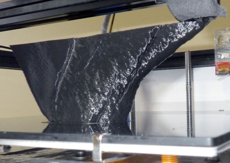
So I tried it on my Printenstein III and it worked perfectly. 1 hour and 20 minutes for the main tooth and 8 minutes for the cut off piece. No supports, completely hollow.
There is a difficult folded bit at the bottom back side so I cut that off and printed it as a separate vase mode print. It needed to have a base anyway so cutting was essential.
Proof that it's hollow:

The original file produces a 13cm tooth (measuring the long edge of the tooth - everyone knows that's how you measure a meg tooth). The 0.6mm nozzle version is a 19cm tooth.
I thought that was great but I've seen Meg and Meg 2 so it seemed a bit of a baby Meg tooth even though the largest fossil Meg tooth ever found was about 19cm.
So I put in my 0.8mm high flow nozzle and printed the tooth again. I used 0.1mm layers and scaled it up a bit more.
This time there was a slight issue on the undercut area but the printer kept going and recovered beautifully.
So the big one being printed with the 0.6mm one beside it for scale:
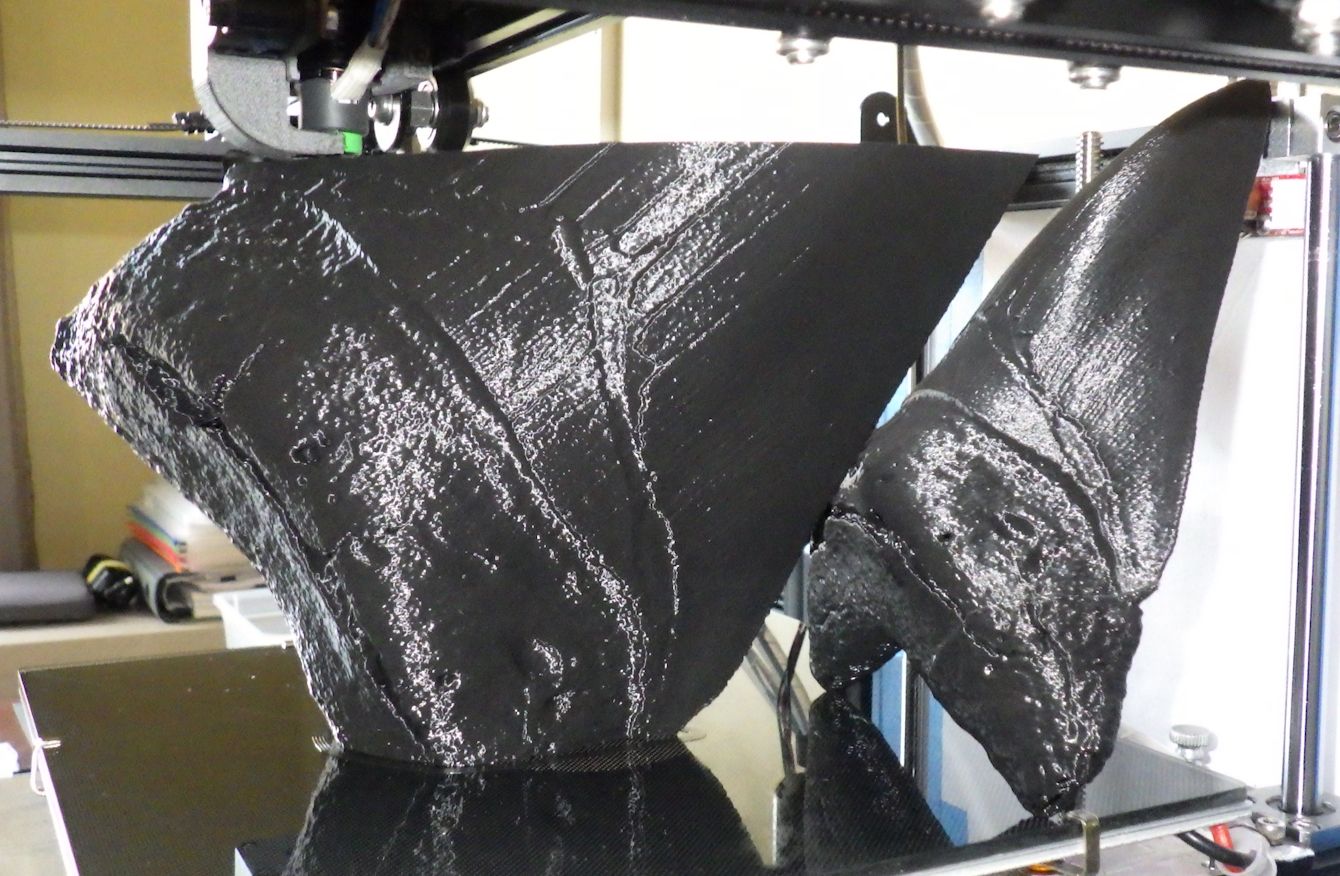
Proof that it too is completely hollow too:

And all three compared:
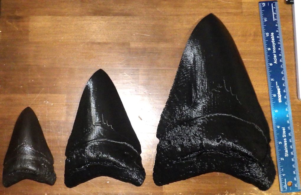
The prints are not flawless because there will be holes in the shell but they can be easily filled:

Everyone needs a giant Meg tooth on their shelf.
Happy printing,
Tony.