Power supplies
-
@SageAardvark As mentioned, there's no fundamental reason you can't connect multiple wires to a single power-supply terminal.
Additionally, there's no fundamental reason you can only connect one wire to the terminal of your boards; you could also run a wire from PSU(+) to B1(+), then a wire from B1(+) to B2(+), then a wire from B2(+) to B3(+) and so on, and do the same for the negative wires. It all works, so long as the connections are good (low-resistance) and the wires are of sufficient gauge. PSU to B1 wires would carry ALL current for all the boards, B1-B2 wires carry all the current minus B1's current draw, etc.
Note that this is NOT the same as wiring PSU(+) to B1(+), B1(-) to B2(+), B2(-) to B3(+), etc. Don't do that.
This is basic series/parallel, voltage/current DC wiring that you can find a lot of info on; a Youtube tutorial or two would probably bring you up to speed to feel comfortable figuring out what will work for your use case.
-
@Maestro ohhh so like over lapping the power cables? That makes more sense, like if I take the one positive terminal, i could over lap cables from the terminal or from the board?
Thank you for responding!
-
If you run the wires in series (ie ps to board 1 then on to board 2 and so on), as Maestro indicates, the first bit of wire carries all the current. This is OK in a lot of cases but do watch the current draw. If you run the build plate heater from any board, I would think this is a somewhat questionable way of going. It would be much better to go with direct lines from the PSU to each individual boards and just stack the cables at the psu if you have to. Use proper terminals on the end of the wire, don't just use bare wire at the psu .
-
@SageAardvark Yes, you can overlap wire connections at the powersupply and/or board. As jens55 mentioned, these should not be bare wires clamped into the terminals. You should first be putting a fork/U-shape connector onto the wire. At that point, as long as the screw on the board/PSU terminal lifts high enough it's a simple matter to stack multiple wires at one terminal. If the terminal is a block style that would take a ferrule connection on the wire (your boards may be this way, depending what they are) then overlapping multiple connections at the terminal is generally not a good idea.
-
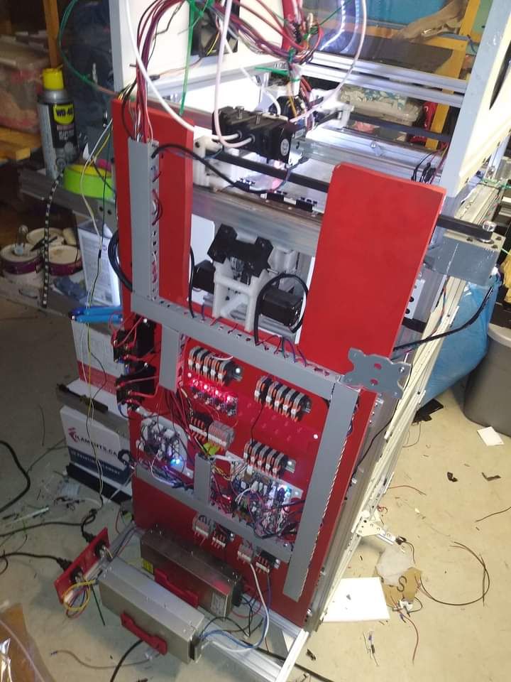
With my CNC build I have used DIN rail connectors to get multiple power terminals and voltages in a sort of buzz bar arrangement, i have found it to be neater and easier if you have the space available
")
-
@jumpedwithbothfeet said in Power supplies:
With my CNC build I have used DIN rail connectors to get multiple power terminals and voltages in a sort of buzz bar arrangement, i have found it to be neater and easier if you have the space available
Likewise
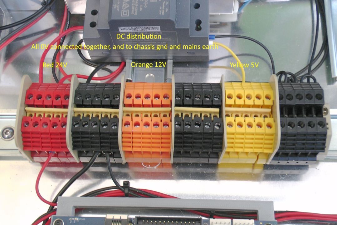
Bus bar jumpers mean that I can use both sides of the connectors, so a single conductor from each PSU gives me 9 x 24v terminals, 9 x 12v terminals and 9 x 5v terminals. More than adequate for anything I can think of

-
@Maestro would it be possible to use this type of connector? Like I conenct the one u cable to the psu and connect this to the wago connector, which is a 1 in 2 out? Would this work? Does the psu also pushout the wattage go to each cable? Like here, https://www.amazon.com/GKEEMARS-Electrical-Connectors-Splicing-Terminal/dp/B09VRTBFTT/ref=mp_s_a_1_3?crid=2916GR814BXLZ&keywords=9+wago+connector+1+in+2+out&qid=1689177809&sprefix=9wago+connector+1+in+2+out%2Caps%2C241&sr=8-3. Would this work?
I am hoping to use a 600 or a 900w power supply. So I don’t know if it would short out the splicing terminal.Thank you for all of the suggestions!
-
@SageAardvark yes you can use those. You can also crimp two cables into a single fork connector to connect to the PSU terminals. Or you can connect two fork terminals to a single PSU terminal - it's easiest if you turn the lower one upside down.
-
@SageAardvark You seem to be going about this the wrong way if you don't mind my saying so. Firstly work out how much power you'll need in Watts - this will help https://docs.duet3d.com/en/User_manual/Connecting_hardware/Power_choosing. Do that for each board then add those values together which will give you the total power required for your PSU. If you use a mains powered bed heater (highly recommended) then you can ignore that because power will be taken directly from the mains and not the PSU.
If you divide the wattage that each board will require, by the voltage, this will give you the current in Amps. You can then select appropriate terminals and cable size to suit. So for example, if the total power requirement for one board is say 72 Watts and you are using 24 Volts, then the current to that board will be 3 Amps.
-
@SageAardvark Those types of connectors would work, but they may not be rated for the full current. You say you plan to use 600 or 900 watt PSUs, but you didn't state voltage. Those connectors are rated for 32 amps. That's fine if your supplies are over-rated, or using 600W, 24V supply. If you're using 600W 12V or 900W supply of 12 or 24V, and are actually using the full power (i.e. running bed and/or enclosure heaters on DC), they are not rated for sufficient current.
PSUs don't push out wattage, they supply voltage, up to a certain current. This loops me back to my suggestion earlier to take in some tutorials about basic DC wiring, to the point that you understand things like voltage/current, and series/parallel connections. Because you can ask all the questions here you want--and people are happy to help--but you can't be confident in your wiring if you don't understand the basics.
-
Din rail the way to go