Wiring Check, pre Tronxy X5SA Pro Overhaul
-
Hi Guys,
After a lot of talk of doing this, I've finally got my 8mm tool-plate back from the machine shop (Dan Sheridan of Rugby (if I'm allowed to say)).
I'm now waiting for a 'gardening grit tray' to arrive to soak and clean the 400 x 400mm tool-plate, then I can start to assemble my build plate.Could I ask yourselves to double check my wiring before I go any further?
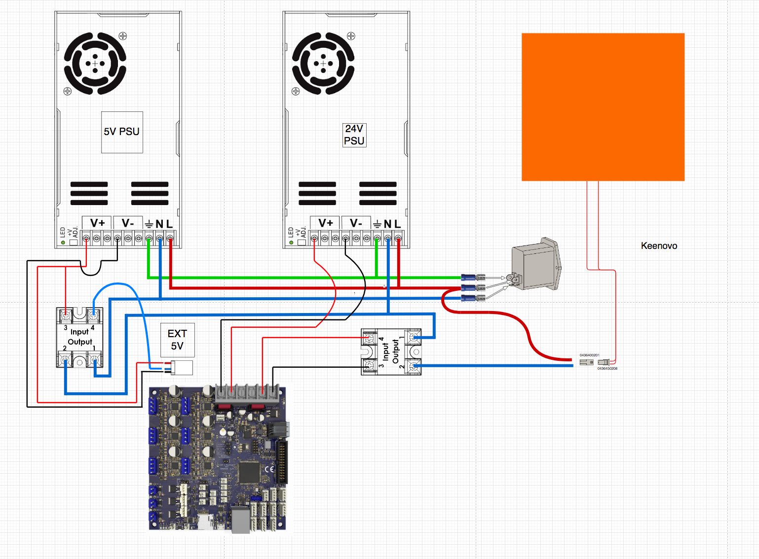
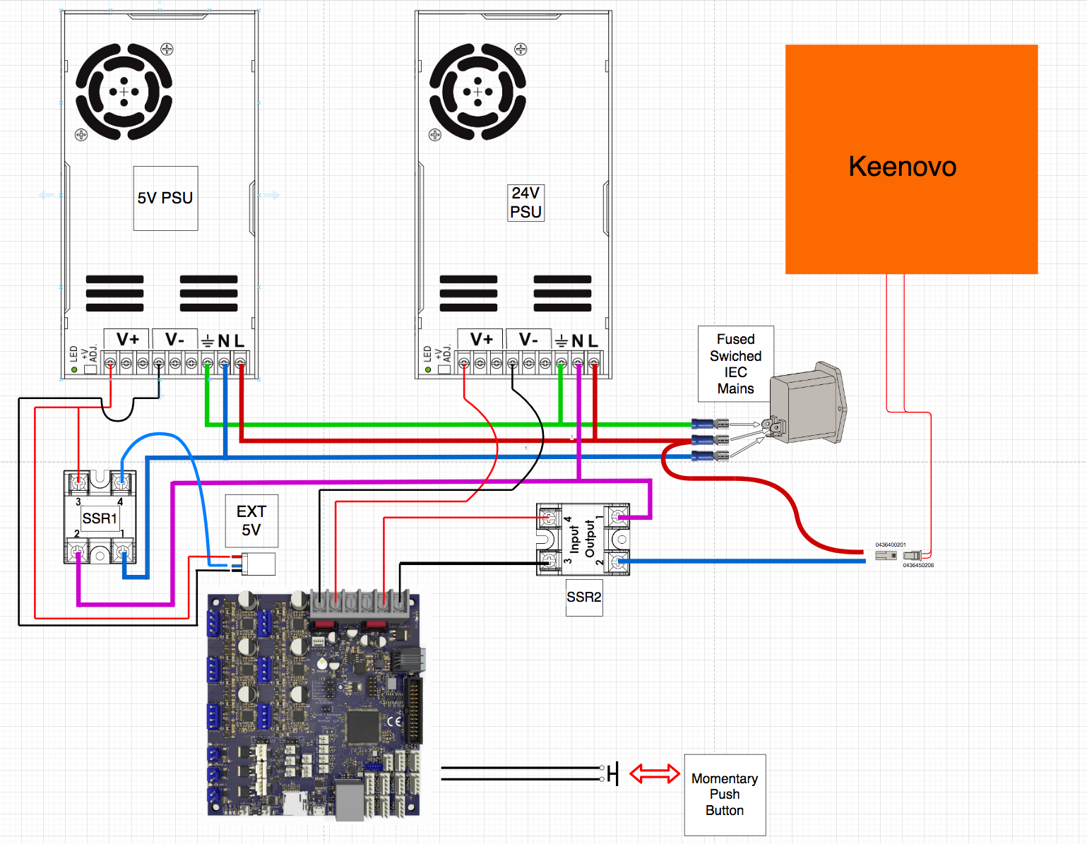
The idea is to use PS-On, following the information kindly provide by Armysolo to a degree;
https://github.com/armysolo/Duet-PS_ONAs I have 2 SSR's I plan on using them both, instead of 1 SSR and 1 mechanical relay.
The thought behind this is that people say you shouldn't rely on just an SSR, but also not on the mechanical relays either, so with having 2 SSR's would this be a safe option, where the 2 SSR would have to be ON to power the bed heater?
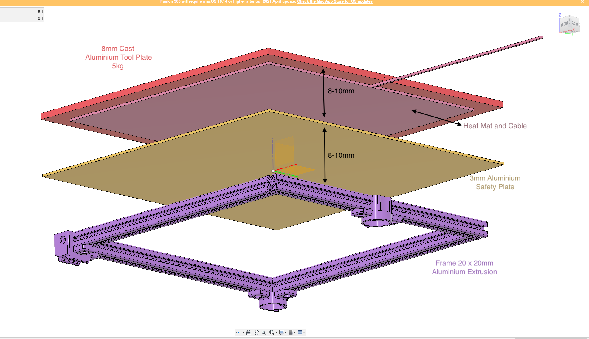
- Please note, I've not included the TCO "THAT IS NEEDED", which will be inline on the power to the bed heater and adhered to the centre of the heater with high temperature silicone.
Under the heater/TCO there will be a 3mm aluminium plate, so should the the heater become detached, it will be captured.
I would like to ask and welcome your thoughts on the proposed wiring diagram and the notion of using the 2 SSR's, mostly on a safety point and of piece of mind.
Dizzwold.
- Please note, I've not included the TCO "THAT IS NEEDED", which will be inline on the power to the bed heater and adhered to the centre of the heater with high temperature silicone.
-
@Dizzwold May I make a suggestion - not related to your wiring? Instead of the 3mm aluminium "safety plate", do what I do and use semi-rigid insulation instead. The type used for under floor heating works well I have found. It will perform the same safety feature if the heater adhesive lets go, but the insulation will do two things. Firstly it will help speed up the bed heat time. Secondly, it will prevent heat conducting into the 2020 frame which will reduce thermal expansion and largely negate the need for kinematic mounts. The downside is that it will take a long time for the bed to cool, which may be problematic if you don't have a removable build surface. Just a thought..........
-
@Dizzwold I'm not familiar with the 5V ps-on function, but:
-
The neutral wire needs a little clarity; above the right-side SSR there are two blue "T"s; I assume the upper one is NOT intended to be a junction?
-
Why all the switching on neutral? I assume the top-right switch is a switch on the mains entering the system? As soon as that switch is on, your bed heater is energized to mains voltage. Seems there's no reason for this; why not switch on line?
Beyond that (and assuming that upper T is not a junction), I would interpret:
- If top-right switch is on, 5V PSU is on.
- If top-right switch is on, bed is energized (I dislike this. Unnecessary)
- Left SSR alone turns on 24V PSU
- Right SSR alone turns on 24v PSU
- Both SSRs on turns on bed and 24v PSU
Edit: I see now the top left "switch" is a mains entry; replace all "switched on" above with "plugged in!"
-
-
@deckingman
Could you please provide a link or product name so that we can take a look at what you are referring to for your alternative material under heated bed?
Thanks! -
Just a quick reply as I'm going out.
Yes, you are correct about the top 'T' not being connected.
I originally had the neutral o/p from the left SSR in purple, but changed this to blue to match the rest of the diagram and missed this. Well spotted.
Here's the original with the neutral o/p in purple;
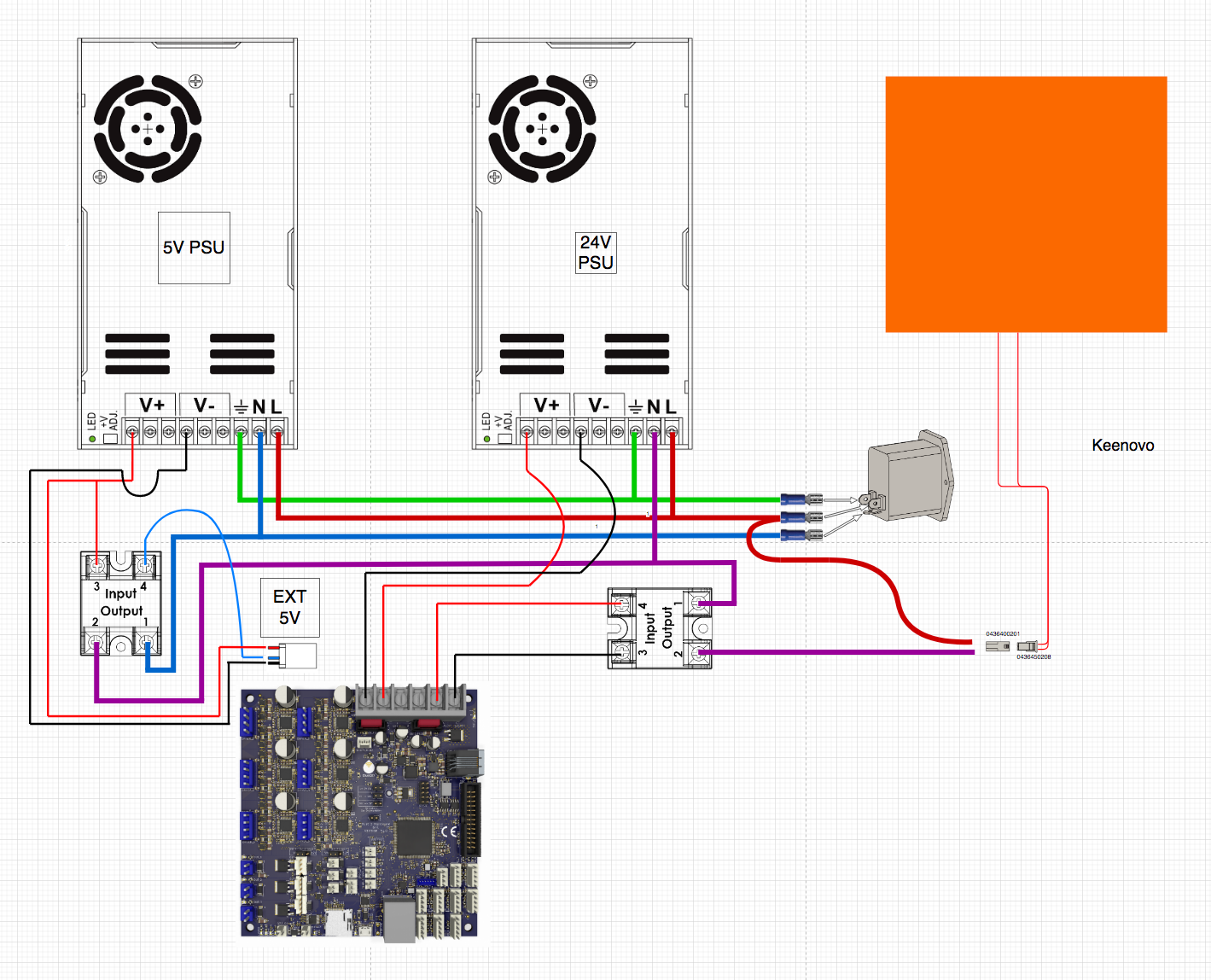
I've also forgot to add a momentary switch to one of the i/o connectors, which may explain some of your other points.
Sorry.
Switches- if your referring to the curved and arched cables, this is to show there not connected and jumping over other cables. Sorry if that was misleading.
-
Kingspan springs to mind in the UK
-
I do have some of that EDPM foil sided foam I was considering as a sandwich filler between the underside of the build plate and 3mm safety sheet.
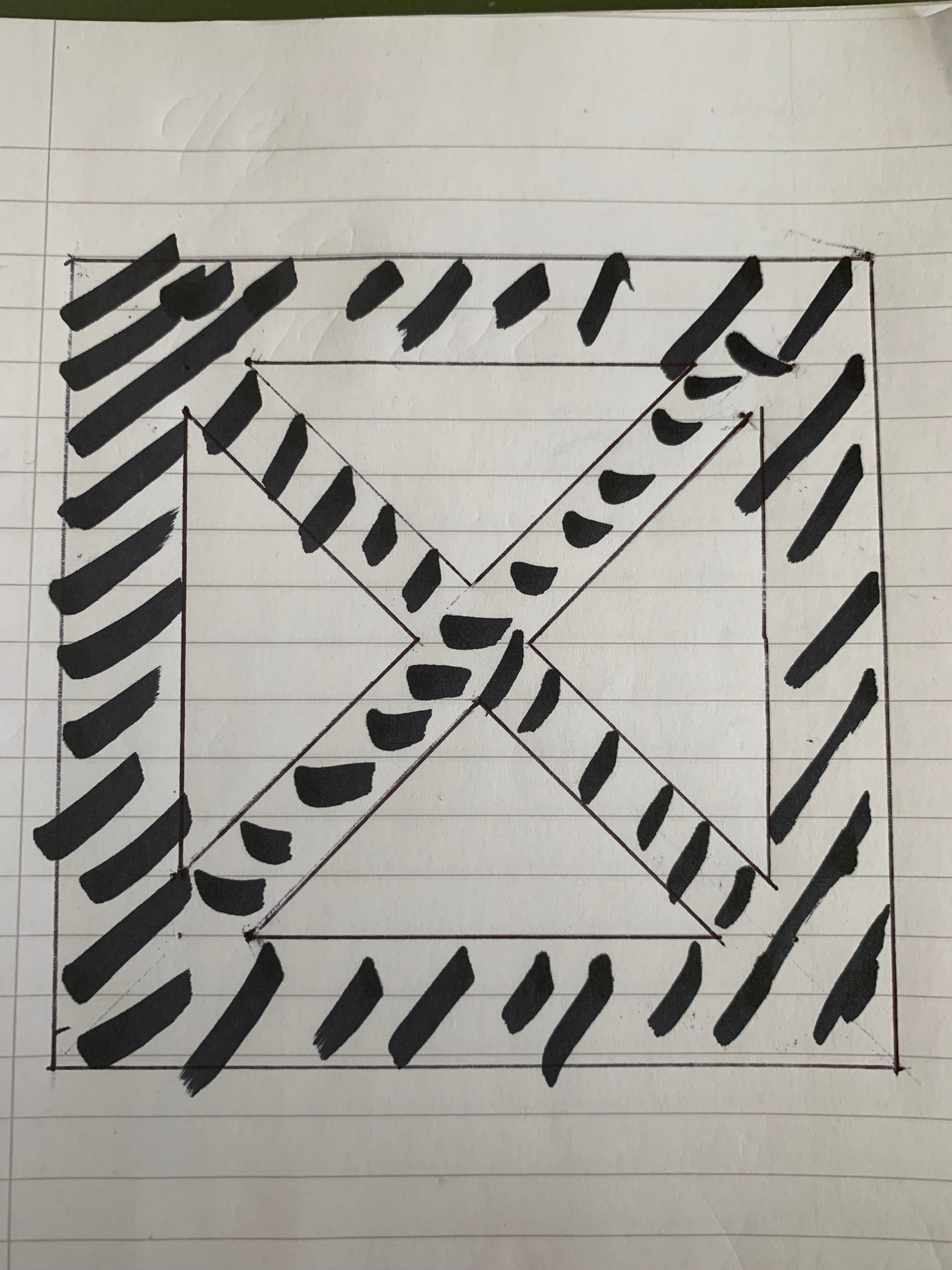
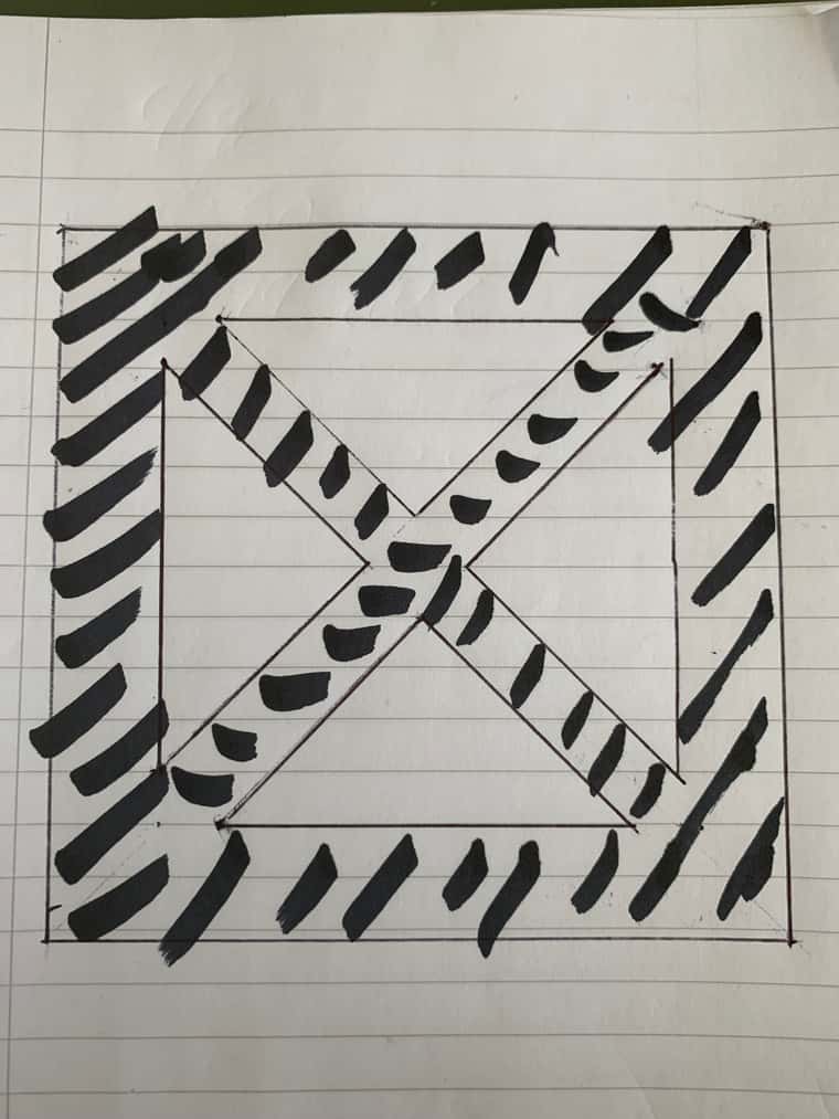
The insulation board is a good idea and option. Regarding your downside point, if cooling the bed was a necessity, shallow channels could always be cut/carved into the insulation board, or you could cut/carve the board into a perimeter square with internal X cross;
-
@Dizzwold I can't off hand find any links to the exact product I used but this is a similar thing https://www.ambient-elec.co.uk/warmup-insulation-boards-8550-p.asp?_=&variantid=8551&gclid=Cj0KCQjwqs6lBhCxARIsAG8YcDihyK_ZMD0gdKDtva8_K--uppZnFHmC0KPM8mWh29fMLrA38YkAtVwaAkKzEALw_wcB
The extended cool down period isn't a problem for me because I use a removable print surface (6mm float glass in my case). So if I want to start another print immediately after one has finished, I simply slide out the glass and insert another sheet.
Cutting shapes or slots in the insulation rather defeats the purpose IMO, because it will lengthen the warm up time.
-
@Dizzwold My reference to a switch was to the mains input; I initially thought it was a switch (kinda looks like a Contura rocker switch from the back), and had edited my post to note the realization it was a mains-power plug. (On that note, labels on things like the mains input and SSR1, SSR2 would help people discuss your schematics in the future).
The purple wire is much clearer.
I was not thrown by the curved wiring or the lack of momentary switch on the IO port. Since I already assumed the purple/blue T was not a junction, everything I said in my original interpretation stands, and none of what I said has been explained away. If my interpretations don't agree with what you're expecting from this schematic, then one of us has made a misinterpretation somewhere.
-
@Maestro said in Wiring Check, pre Tronxy X5SA Pro Overhaul:
If my interpretations don't agree with what you're expecting from this schematic, then one of us has made a misinterpretation somewhere.
No, not at all and please don't get me wrong as written words can be read wrong. I'm grateful for the feed back, and this is why I've posted before attempting any wiring. I had read your edit, but with quoting the "Top Left Switch", the only thing I could assume you where describing in the top left was the cable jumping over another.
The idea I have is as follows;
Mains from fused switched IEC. When switched ON, 5v PSU is ON and Duet is 'low power mode' as such.
Momentary switch is pressed (with Trigger, M80, M950, M581 & M81 code). This will switch ON SSR1 via PS-ON, providing Neutral power to to 24v PSU (Live already connected), and also to the I/P of SSR2.When the Duet is asked to heat the bed heater it will switch ON SSR2. The Neutral line is broken until you ask the duet to turn the heater On.
Well that's the idea I have in mind. Weather my wiring is correct or not is another matter?
With regards to switching the neutral line. Most of what I've read in the past when others were designing and posting their wiring diagrams while switching the live, they where most often advised to switch the neutral instead. I appreciate that the neutral, when completing the circuit does go back to live. I've just understood this to be better practice than directly switching the live.
-
@Dizzwold I didn't mean anything aggressive/argumentative by my statement; I'm not put off in any way, it's all good. Just when you said that the I/O switch missing might explain some of my other points, I wanted it to be clear that it didn't.
I have trouble with left/right (not dyslexic in any way, just don't process those two particular words correctly for some reason!). I was careful through the post, but then got it wrong in my edit comment. Apologies for the confusion!
I do not agree that switching should be on neutral. In DC circuitry it's often sensible/preferable to switch to ground, but in dealing with mains voltage this is not good practice. If you're cutting off/on mains voltage to an appliance (which the printer is, for all practical purposes) switching should be done either on line/load or on both line and neutral, and you should do it as close to mains entry as possible.
Imagine the following scenario; SSR2 faults closed. The Duet detects a heater fault, and turns off the SSR2. Faulted SSR2 continues to overheat the bed. Eventually Duet detects that things are now way out of spec, and shuts down SSR1. Ok, the bed is now "off". However, the bed heater is still energized to line voltage; you have a potentially defective component (it did just potentially overheat) that has 110/220V running to it, possibly distributing that potential to the metal bed or elsewhere. Additionally, if it has a good enough (high-current enough) short, then it may not even be off if there isn't a ground-fault interrupt in the system.
That's the biggest issue, but similarly, the line and neutral terminals of both PSUs are always live when the mains entry is plugged in/switched on (not needing an SSR failure, just by default with this wiring, they're live). The PSUs are not "on", because their neutral line is open, but not being on is not the same as not being dangerous; they're still at 110/220v potential.
If SSR2 fails closed and the left is off/open, there is NO terminal or wire on your mains circuit that isn't energized. The same is true if SSR1 faults closed and the other is off/open. If both SSRs are functional and off... there's no terminal or wire on the mains circuit that isn't energized! The top blue wire is safer than others, but it's not safe.
When dealing with mains voltage, we want "off" to mean both off and deenergized to the extent possible, which means switching the line voltage as early as possible.
As one additional note; personally, I would prefer not to have two SSRs as my safety cut, simply because they're similar devices and so will have similar failure modes. I.e., if something causes one to fail, it may well cause the other to fail as well. So, I would vote the SSR plus mechanical relay route as safer. Or, thermal fuse on the bed. This is down in the weeds level though; if I also already had two SSRs I'm not sure I would take the trouble to switch to an SSR and relay. The switching line instead of neutral is the low-hanging fruit here.
Edit: P.S., IMO the best under-bed insulation is carbon-felt welding blanket material.
-
Thank you for your detailed explanation, I'm very grateful for this as your scenario has made me understand your points fully and realise the potential danger issues.
Thank you.I'll have to have a rethink for safety sake and draw up something else.
This is the exact reason I came and asked my question.
Regarding bonding the silicone heat mat. Would it be a good idea to rough up the underside of the tool plate to add a 'key' for the high temperature silicon to bond the mat?
Now on to 3M 468-MP to bond the PEI sheet. The PEI sheet I purchased was from gizmo-dorks on amazon.com (US), 16" x 16" so 406mm, but instead of coming with one sheet of 3M 468-MP it came with 4 smaller 203 x 203mm.
Well what a game I had with that. I had to remove the whole lot using masking tape to lift it all off.Does anyone have any other solution to bond a PEI sheet to Aluminium Tool Plate?
-
@Dizzwold You're welcome. I'm sure you can sort out a line-switched configuration that will still accomplish your goals.
I would suggest roughing the aluminum for silicone adhesive. Silicone will not chemically bond the aluminum, so the more mechanical key you can give it the better. I like Permatex Aviation Form-A-Gasket, as it's less viscous before curing than most RTVs, and with even a little surface roughness it never seems to peel.
-
@Maestro said in Wiring Check, pre Tronxy X5SA Pro Overhaul:
I like Permatex Aviation Form-A-Gasket
Ooh, that's interesting and a good find. Looks like there's only one place in the UK that sells it at sensible price;
Ebay Seller UKFrom your experience of 'Form A Gasket' and reading the instructions it sounds like you apply it similar to a contact adhesive by coating both surfaces to be bonded, until skinning over.
Would 118ml (4 fl/oz), be enough to cover both my 350 x 350mm heat mat and the bed, then apply a second perimeter coat over the edges?@Maestro said in Wiring Check, pre Tronxy X5SA Pro Overhaul:
I'm sure you can sort out a line-switched configuration that will still accomplish your goals
Yeah, we'll get there. Thank you for elaborating on your points and feedback, as I couldn't see the wood for the tree's to begin with.
From a safety point, I'm very grateful. -
@Dizzwold That's correct; you coat both surfaces and let if flash off before joining. If you want the outside edges of your bed to stay clean (i.e. the 8mm thickness sides) I would suggest taping them off. 4oz should be plenty for one 350x350 bed.
-
Damn, that Form A Gasket is nasty stuff.
Did you have any issues with curing?
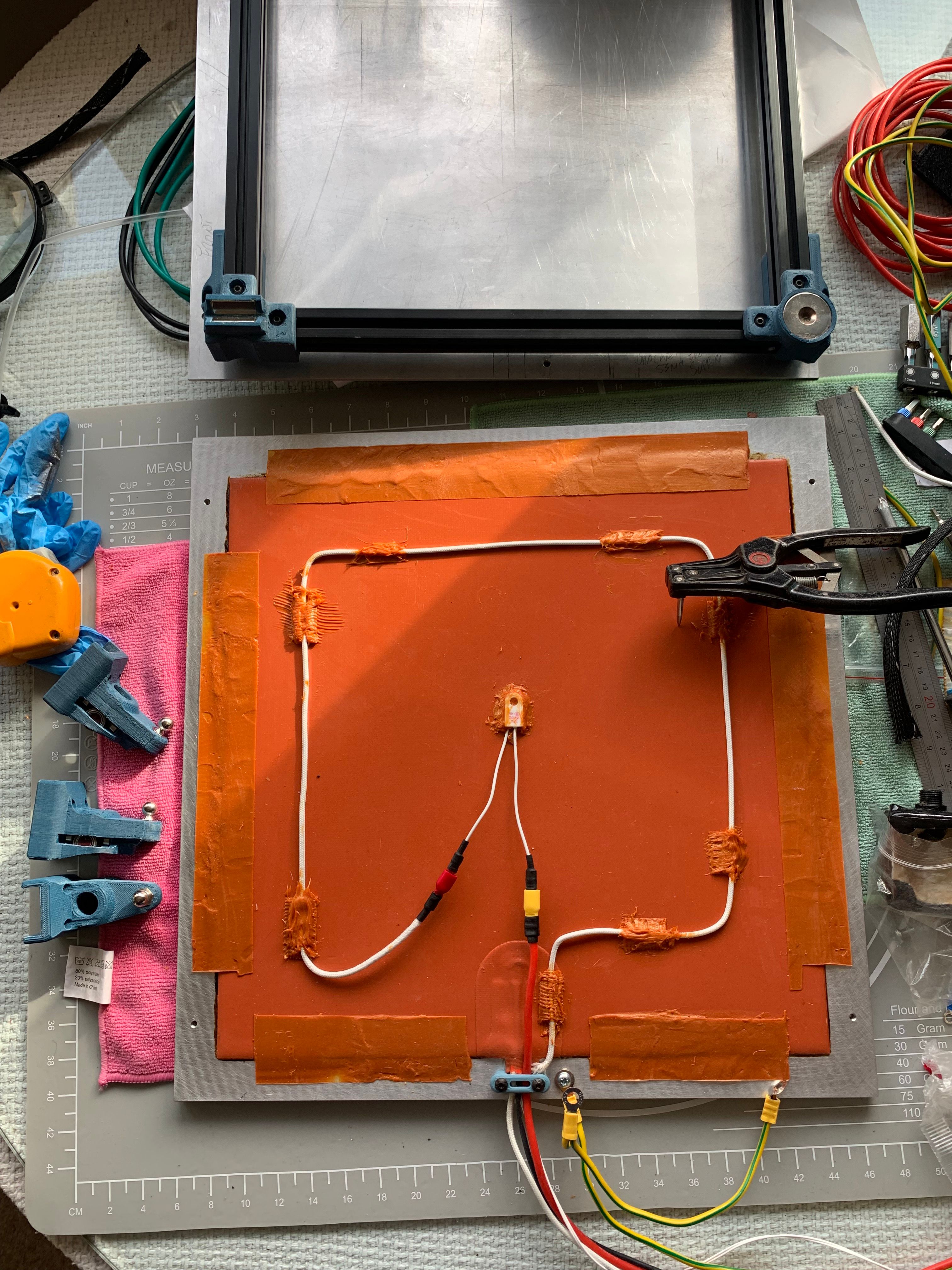
I masked of the perimeter of my tool plate, applied the Form A Gasket to the tool plate and then to the heat mat. By the time I started applying to the heat mat the tool plate was already skinning over.
I removed the masking tape a couple of hours later.
I've not yet added an addition coat a round the perimeter (to the top edge of the heat mat and tool plate), as I'm a little concerned about the curing.
Due to the Form A Gasket being "a possible carcinogenic", I decided to do this in my shed where it was around 20˚c during the day and 15˚c during the night. It was still wet after 24hrs.
I've then brought it into the house for another 24 hrs and it's still like chewing gum?
Is this how the fully cured product should be, or is something wrong there?
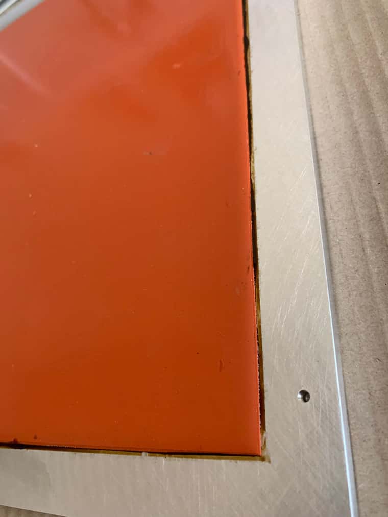
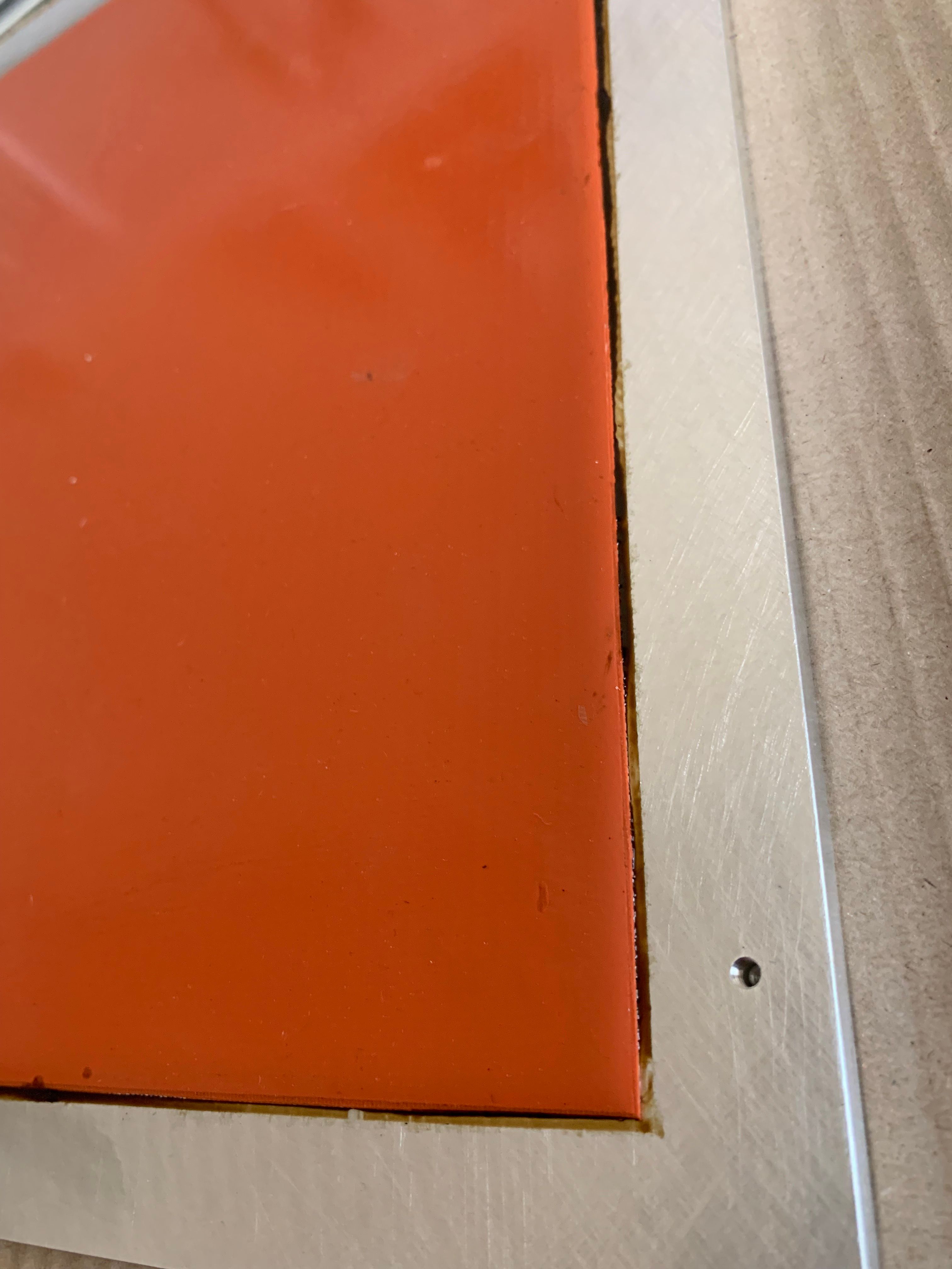
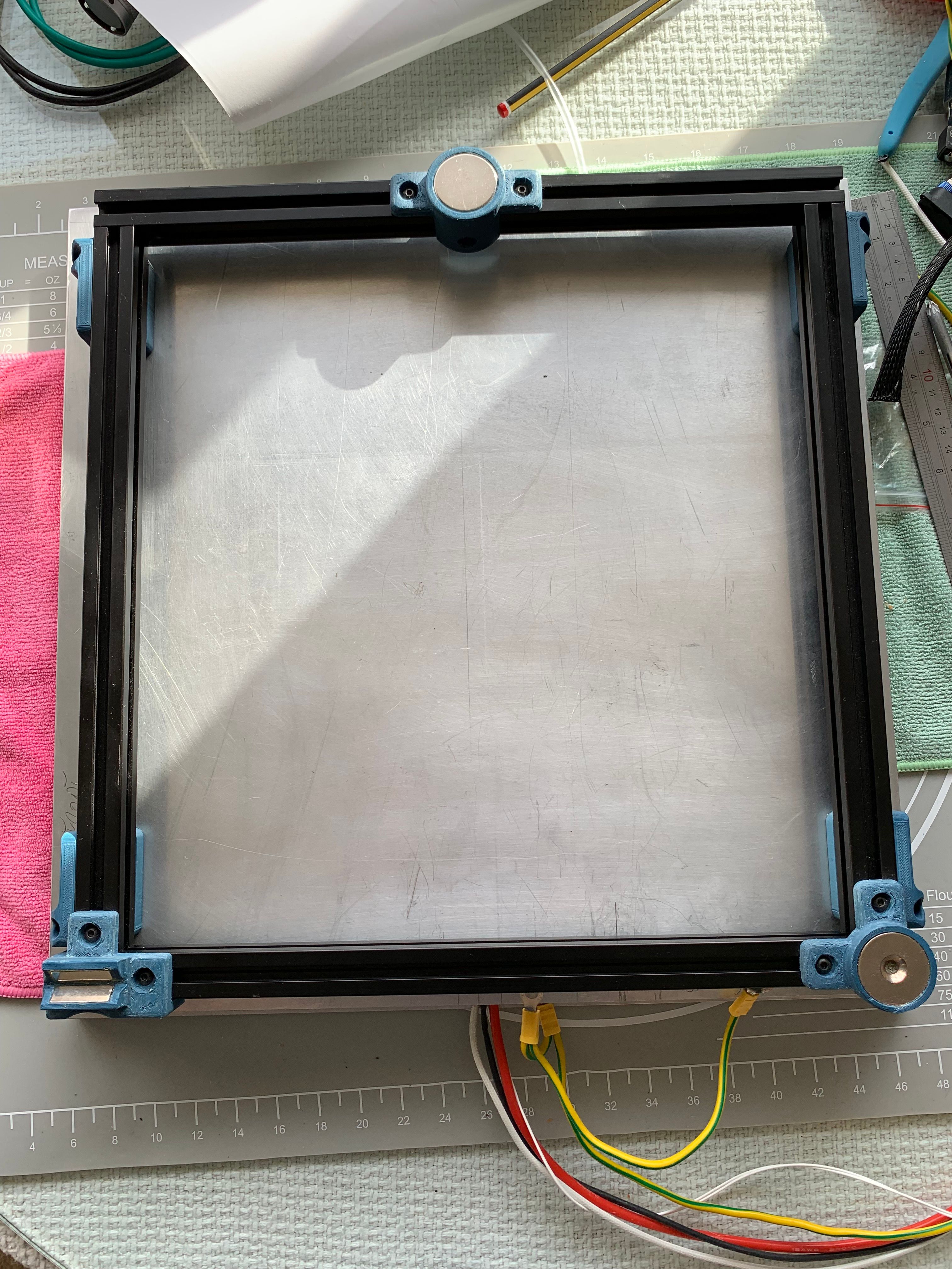
Although I've got to redesign the wiring, something else I'd missed off the diagram was the earth lead to the bed. That's what the extra threaded hole is for next to the cable clamp in the picture.
-
@Dizzwold The bed is not a great form-factor for rapid curing, as the solvent escape is only around the perimeter for a relatively large area of sealant. So, it's going to take a while for the solvent from the center of the bed to propagate all the way out; I wouldn't expect it to fully cure in 24 hours, or even 48. The form-a-gasket is also relatively soft when cured; it stays a bit tacky and pliable, and that is expected/desired, so keep that in mind also when judging how far it has to go. Even when it's considered fully cured for service, it will still feel a bit soft and sticky.
-
Can I be cheeky, and would you be kind enough to check my new wiring diagram?
I would appreciate a second opinion and to find any possible fault scenarios before I move forward and start to physically wire it up.
I may also include, as you previously suggested a mechanical relay in place of SSR1. The wiring for this wouldn't change greatly as it would only need a Signal cable running from the 5v psu.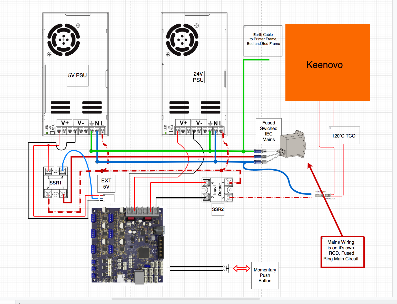
Can I also take you back to one of your comments;
@Maestro said in Wiring Check, pre Tronxy X5SA Pro Overhaul:
Additionally, if it has a good enough (high-current enough) short, then it may not even be off if there isn't a ground-fault interrupt in the system.
Was this comment due to that I hadn't documented the Earthing to the Bed, Bed Frame and Printer Frame/That my mains circuit feeding my printer room/workshop is on it's own individual circuit, fused and RCD protected, or is there something else I need to consider here?
Dizzwold.
-
@Dizzwold I think this is a much-improved configuration, and nothing jumps out to me as problematic. As you've probably worked out, the only energized wire while things are off would be the solid-red line, which is a huge reduction in energized points compared to the last setup.
@Dizzwold said in Wiring Check, pre Tronxy X5SA Pro Overhaul:
Was this comment due to that I hadn't documented the Earthing to the Bed, Bed Frame and Printer Frame/That my mains circuit feeding my printer room/workshop is on it's own individual circuit, fused and RCD protected, or is there something else I need to consider here?
Yes, RCD circuit protection adresses this concern. The issue was that with the bed always energized--and no mention of ground-fault protection--a short at the bed would leave the bed both electrically dangerous and potentially still functionally "on" as a heater. This is because the load wire doesn't care one bit whether it closes connection to neutral or to ground, and your original config severed connections to neutral, but ground is still there to potentially connect to if things go physically awry (i.e. melt). A ground-fault interrupt can make the distinction of current passing through ground versus neutral and should trip to when a circuit closes to ground, so you would no longer expect a short-circuit to the bed to remain live.
-
Thank you for taking the time to check this over. I'm most grateful.
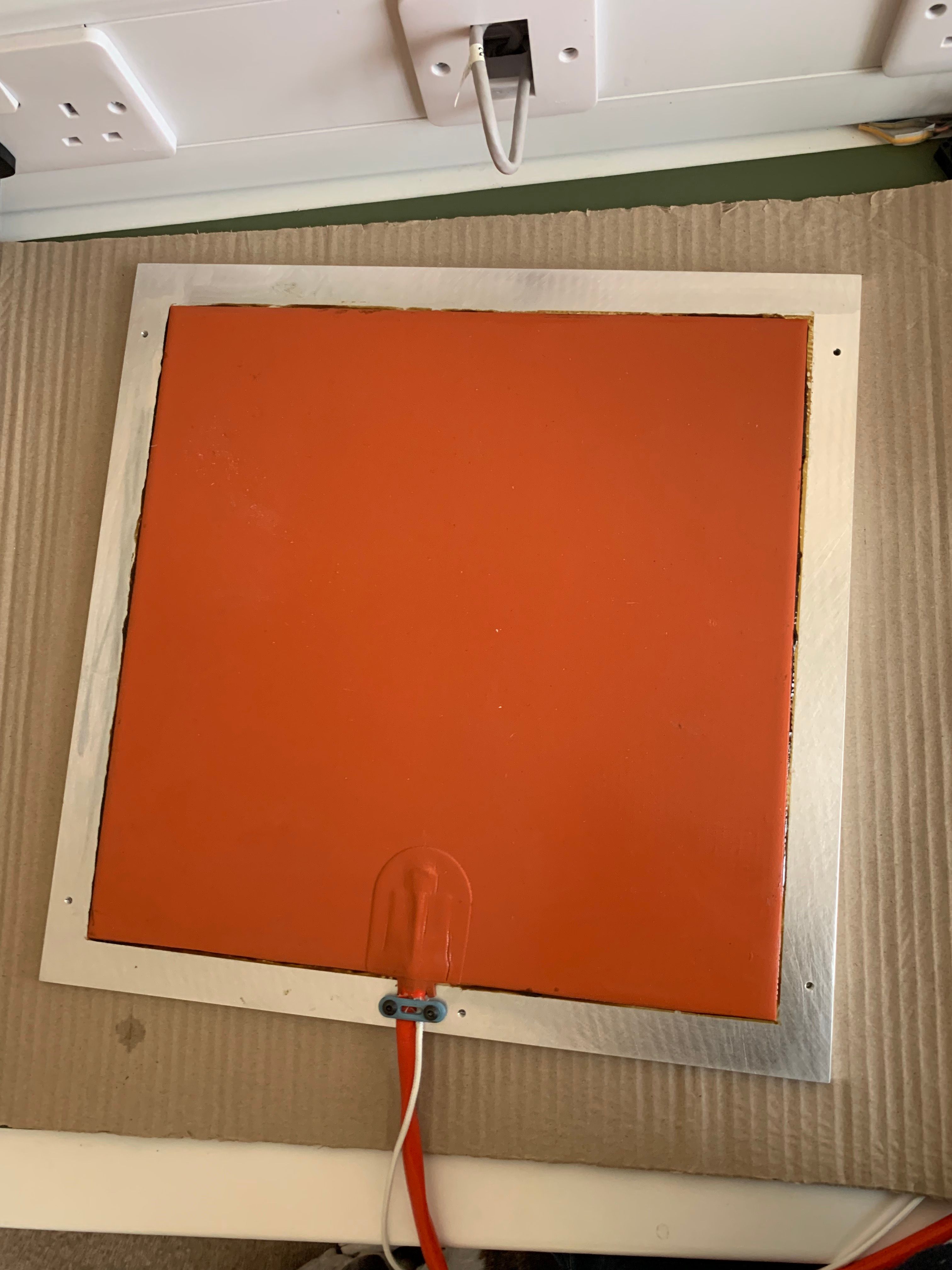
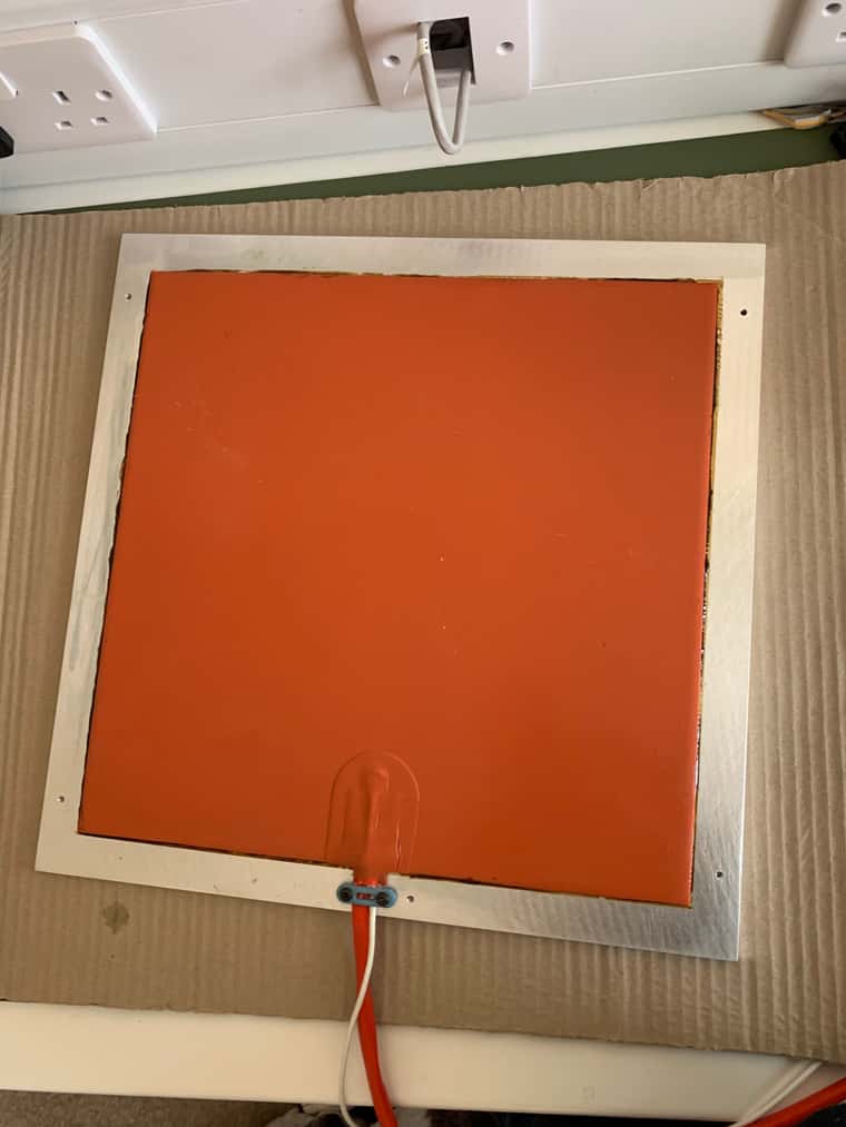
Here's where I'm at currently with the bed, where the Earth cables for the bed frame and 3mm safety plate are loose. The cable running around the inner perimeter of the heat mat is the lead coming from the heater, to the TCO. I had thought about cutting this down, but then thought to just stick it in-place.

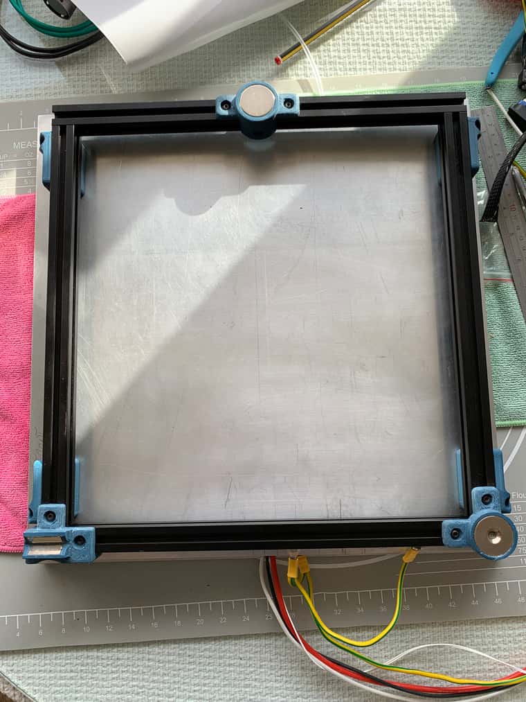
I've also got some of that aluminium foil/closed cell foam of various thicknesses that I can also add, to sandwich between the heater and safety sheet if want.
Thank you again for you time and input.
Dizzwold.