Ortho axis compensation - error
-
@droftarts
@T3P3Tony
Slight problem,
with the new firmware, my printer moves diagonally on XY and seems to print very thick lines. It is a corexy printer.
Also it says it can't save my wifi ssid, so my ssid and password are there in plain text (I censored them).
This is my config.g:; Configuration file for Duet WiFi (firmware version 2.03) ; executed by the firmware on start-up ; ; generated by RepRapFirmware Configuration Tool v2.1.2 on Tue Nov 05 2019 14:13:07 GMT-0800 (Pacific Standard Time) ; General preferences G90 ; send absolute coordinates... M83 ; ...but relative extruder moves ;M550 P"Ender 4 CoreXY" ; set printer name M550 P"I`ll melt with you" ; set printer name M587 S"***" P"***" M667 S1 ; select CoreXY mode ; Network ;M551 P"reprap" ; set password M552 S1 ; enable network M586 P0 S1 ; enable HTTP M586 P1 S1 ; enable FTP M586 P2 S1 ; enable Telnet ; Drives M569 P0 S1 ; physical drive 0 goes forwards M569 P1 S1 ; physical drive 1 goes forwards M569 P2 S1 ; physical drive 2 goes forwards M569 P3 S1 ; physical drive 3 goes backwards M584 X0 Y1 Z2 E3 ; set drive mapping M92 X79.95 Y79.95 Z1599.945 E96.36 S16 ; set steps per mm (256x microstepping) (new 2mm pitch 1 start 2mm lead lead screw multiplies steps by 4) M350 X256 Y256 E256 Z256 I0 ; configure 256x microstepping without interpolation ;M92 X629.784 Y644.168 Z12,882.448 E770.88 ; set steps per mm (256x microstepping) (new 2mm pitch 1 start 2mm lead lead screw multiplies steps by 4) M203 X18000.00 Y18000.00 Z1200.00 E1800.00 ; set maximum speeds (mm/min) M906 X1000 Y1000 Z1500 E1000 I35 ; set motor currents (mA) and motor idle factor in per cent M84 S30 ; Set idle timeout ; Axis Limits M208 X0 Y0 Z0 S1 ; set axis minima M208 X212 Y220 Z300 S0 ; set axis maxima ; Endstops M574 X1 S1 P"xstop" ; configure active-high endstop for low end on X via pin xstop M574 Y1 S1 P"!ystop" ; configure active-low endstop for low end on Y via pin ystop M574 Z1 S1 P"zstop" ; configure Z-probe endstop M591 D0 P7 C"e0_stop" S0 E51 L4.14 R85:110 A1 ; Pulse-type filament monitor on pin e0_stop, enabled, sensitivity xmm/pulse, allowed movement x% to x%, check every xmm ;M591 D0 P2 C"e0_stop" S0 ;Filament Sensor, E0, High signal, E0 endstop port, monitoring enabled ; Z-Probe M558 P9 C"^zprobe.in" H5 T2000 ; Set Z probe type/mode 9. H=Dive Height. F=Speed the bed moves (for BLTouch) M950 S0 C"exp.heater3" ;Create a GPIO/Servo pin index using GPIO expansion pin 8 (heater 3) ;M558 P5 C"!zprobe.in+zprobe.mod" H5 F120 T6000 ; set Z probe type to switch and the dive height + speeds and set inverted (for inductive probe) ;G31 P500 X0 Y0 Z1.49 ; set Z probe trigger value, offset and trigger height (inductive) G31 P25 X-44 Y-3 Z3.50 ; set Z probe trigger value, offset and trigger height (BLTouch) ;M556 S50 X0 Y0 Z0 ; set orthogonal axis compensation parameters ;M557 X0:167.9 Y3:216.9 P2:2 ; define mesh grid (4 points) ;M557 X168:212 Y3:220 P3:3 ; define mesh grid (9 points) ;M557 X40:230 Y10:220 S32 ; define mesh grid (42 points) ;M557 X40:212 Y10:220 P8:8; define mesh grid (64 points) M557 X0:167.9 Y3:216.9 P10:10; define mesh grid (100 points) ;M557 X40:212 Y10:220 S24.57:30 define mesh grid (64 points) ; Heaters ;M305 P0 T100000 B4138 R4700 ; set thermistor + ADC parameters for heater 0 (Depreciated in v3.0+) ;M305 P1 T100000 B4138 R4700 ; set thermistor + ADC parameters for heater 1 (Depreciated in v3.0+) M308 S0 P"bedtemp" Y"thermistor" T100000 B4138 C7.06e-8 ; configure sensor 0 as thermistor on pin bedtemp M950 H0 C"bedheat" T0 ; create bed heater output on bedheat and map it to sensor 0 M143 H0 S115 ; set temperature limit for heater 0 to 115C M140 H0 ; map heated bed to heater 0 ;M308 S1 P"e1temp" Y"thermistor" T100000 B4138 C7.06e-8 ; configure sensor 1 as thermistor on pin e0temp M308 S1 P"e1temp" Y"thermistor" T100000 B4956 C1.587780e-7 ; configure sensor 1 as thermistor on pin e0temp M950 H1 C"e0heat" T1 ; create nozzle heater output on e0heat and map it to sensor 1 M143 H1 S310 ; set temperature limit for heater 1 to 310C ; Fans M950 F0 C"fan0" Q500 ; create fan 0 on pin fan0 and set its frequency M106 P0 C"Nozzle" S0 H-1 ; set fan 0 name and value. Thermostatic control is turned off M950 F1 C"fan1" Q500 ; create fan 1 on pin fan1 and set its frequency M106 P1 C"Heatsink" S0.1 L0.55 X1.0 H1 T100:300 ; set fan 1 name and value. Thermostatic control is turned on M950 F2 C"fan2" Q3000 ; create fan 2 on pin fan2 and set its frequency M106 P2 C"LEDs" S0 H-1 ; set fan 2 name and value. Thermostatic control is turned off ; Tools ;M563 P0 D0 H1 F1:2:0 ; define tool 0 M563 P0 D0 H1 S"Hotend" F0 ; define tool 0 ;M563 P1 H0 S"Bed" ; define tool 1 G10 P0 X0 Y0 Z0 ; set tool 0 axis offsets G10 P0 R0 S0 ; set initial tool 0 active and standby temperatures to 0C ;G10 P1 R0 S0 ; set initial tool 1 active and standby temperatures to 0C ; Custom settings M307 H0 R0.095 K0.092l0.000 D16.36 E1.35 S1.00 B0 ;Bed PID Tuning M307 H1 R1.633 K0.371:0.028 D11.66 E1.35 S1.00 B0 V23.8 ;Hotend PID Tuning M376 H3 ; Hnnn Height (mm) over which to taper off the bed compensation M929 S1 ;M929 P"eventlog.txt" S1 start logging to file eventlog.txt S0= stop logging M929 S0 - stop logging *do not delete log file while logging* M566 X2400 Y2400 Z24.00 E150.00 ; set maximum instantaneous speed changes (Jerk) (mm/min) ;M566 X200 Y200 Z24.00 E150.00 ; set maximum instantaneous speed changes (Jerk) (mm/min) (old) M201 X2400 Y2400 Z600 E3000.00 ; set accelerations (mm/s^2) ;M203 X6000.00 Y6000.00 Z720.00 E1200.00 ; set maximum speeds (mm/min) (Defaults) ; Sensorless Homing ;M915 X S4.9 R0 F0 H40 ; set X sensitivity, log when stall, unfiltered ;M915 Y S4.9 R0 F0 H40 ; set Y to sensitivity, log when stall, unfiltered ;M915 Z S4.95 R1 F0 H60 ; set Z sensitivity, log when stall, unfiltered ;M575 P1 B57600 S3 ;Use Paneldue port for serial communications instead of USB, set to raw mode with checksums M575 P1 B57600 S1 ;Paneldue Settings ;M575 P0 B250000 ;Main Serial Settings ; Miscellaneous M911 S10 R11 P"M913 X0 Y0 G91 M83 G1 Z3 E-5 F1000" ; set voltage thresholds and actions to run on power loss ;M452 C"!exp.heater4" F200 ; laser uses heater4 pin, PWM frequency 200Hz M950 P3 C"exp.heater4" Q500 ; allocate GPIO port 0 to heater4 on expansion connector for Laser, 500Hz. "M42 P3 S1.0" to activate laser. M556 S1 X0.0183381 Y-0.0110953 Z-0.0060452 ;Axis skew compensation M572 D0 S0.3 ;Pressure advanceEDIT
replaced m667 s1 with m669 k1 and all is well -
@osterac do not have M587 in config.g its probably giving the error because the SSID and password are already sent. They should only need to be sent once.
Thanks for confirming that M556 works as expected in 3.5b2
-
@T3P3Tony
Unfortunately I'm still having the problem where it is printing very thick lines. They are ~1.5mm thick when they should be 0.8. The prints look awful.PS I also get this when I run my config.g file
Error: Heater 1 not switched on due to bad modelThe number of lines in the wall is different in the gcode vs what actually printed
YACS xy.gcode
It's also way out of square (more than before)
-
@osterac
I tried wiping my SD and starting from scratch with reprap config tool and RRF 3.4.5 but the problem remains -
@osterac
It's doing another weird thing. When I uncomment this line in the config file:M452 C"!exp.heater4" F200 ; laser uses heater4 pin, PWM frequency 200HzThe web interface looks like this:
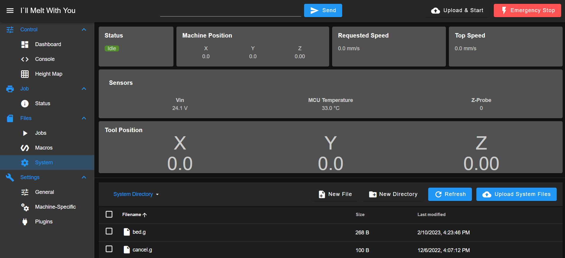
It goes back to normal when I comment that line out and restart the mainboard (but not if I just run the config.g file).
Ideas?
Thanks -
@osterac Where did you get the config.g file from? Because the one you posted earlier may have come from the RepRapFirmware configuration tool originally, but has had a lot of edits to it. It looks like it was originally for RRF v2, and it has been adapted for RRF v3. To try and answer you questions:
M556 ortho axis compensation: It has been highlighted in this thread https://forum.duet3d.com/post/307701 that the Marlin uses the resulting skew factor differently that RRF. I need to check this, but it does seem to be the case. You should change the sign of the answer the calculator macro gives, ie if it says "0.0183381" use "-0.0183381".
Thick extrusion lines: Have you calibrated your extruder? You seem to have changed the extrusion steps per mm around. Also, you are using x256 microstepping on all axes. Use x16 with interpolation. x256 micorstepping puts an extra burden on the processor, and will generally limit speeds, for no practical gain. There are a few cases where it is worth using a higher microstepping rate, but this use case isn't one of them.
Error: Heater 1 not switched on due to bad model - there is a typo in your M306 command:
M307 H0 R0.095 K0.092l0.000 D16.36 E1.35 S1.00 B0 ;Bed PID Tuning
The "l" in the K parameter should be a ":"M452 switches the printer into laser cutter mode. RRF support 3D printer, CNC and Laser modes. See M450, M451, M452 and M453. You can check which mode it is in by sending M450, and switch back to 3D printer mode by sending M451. You don't need M452 in your config.g unless you have a laser cutter tool.
Ian
Bed-slinger - Mini5+ WiFi/1LC | RRP Fisher v1 - D2 WiFi | Polargraph - D2 WiFi | TronXY X5S - 6HC/Roto | CNC router - 6HC | Tractus3D T1250 - D2 Eth
-
@droftarts
So this is the new config file from RRF config tool, I made the changes you mentioned. Some of the stuff in custom settings is copied over from my old config.g, but most of it is disabled for now.; Configuration file for Duet WiFi (firmware version 3.3) ; executed by the firmware on start-up ; ; generated by RepRapFirmware Configuration Tool v3.3.15 on Fri Feb 10 2023 08:23:47 GMT-0800 (Pacific Standard Time) ; General preferences M575 P1 S1 B57600 ; enable support for PanelDue G90 ; send absolute coordinates... M83 ; ...but relative extruder moves M550 P"I`ll Melt With You" ; set printer name M669 K1 ; select CoreXY mode ; Network M552 S1 ; enable network M586 P0 S1 ; enable HTTP M586 P1 S1 ; enable FTP M586 P2 S1 ; enable Telnet ; Drives M569 P0 S1 ; physical drive 0 goes forwards M569 P1 S1 ; physical drive 1 goes forwards M569 P2 S1 ; physical drive 2 goes forwards M569 P3 S1 ; physical drive 3 goes forwards M584 X0 Y1 Z2 E3 ; set drive mapping M350 X16 Y16 E16 Z16 I1 ; configure 16x microstepping with interpolation M92 X79.95 Y79.95 Z1599.945 E96.36 S16 ; set steps per mm (new 2mm pitch 1 start 2mm lead lead screw multiplies steps by 4) M566 X900.00 Y900.00 Z60.00 E120.00 ; set maximum instantaneous speed changes (mm/min) M203 X15000.00 Y15000.00 Z1500.00 E1200.00 ; set maximum speeds (mm/min) M201 X1000.00 Y1000.00 Z20.00 E250.00 ; set accelerations (mm/s^2) M906 X1000 Y1000 Z1500 E1000 I30 ; set motor currents (mA) and motor idle factor in per cent M84 S30 ; Set idle timeout ; Axis Limits M208 X0 Y0 Z0 S1 ; set axis minima M208 X212 Y220 Z300 S0 ; set axis maxima ; Endstops M574 X1 S3 ; configure sensorless endstop for low end on X M574 Y1 S3 ; configure sensorless endstop for low end on Y M574 Z1 S2 ; configure Z-probe endstop for low end on Z ; Z-Probe M950 S0 C"exp.heater3" ; create servo pin 0 for BLTouch M558 P9 C"^zprobe.in" H5 F120 T6000 ; set Z probe type to bltouch and the dive height + speeds G31 P500 X0 Y0 Z3.6 ; set Z probe trigger value, offset and trigger height M557 X0:167.9 Y3:216.9 P10:10 ; define mesh grid ; Heaters M308 S0 P"bedtemp" Y"thermistor" T100000 B4138 ; configure sensor 0 as thermistor on pin bedtemp M950 H0 C"bedheat" T0 ; create bed heater output on bedheat and map it to sensor 0 M307 H0 B0 S1.00 ; disable bang-bang mode for the bed heater and set PWM limit M140 H0 ; map heated bed to heater 0 M143 H0 S115 ; set temperature limit for heater 0 to 115C M308 S1 P"e1temp" Y"thermistor" T100000 B4138 ; configure sensor 1 as thermistor on pin e0temp M950 H1 C"e0heat" T1 ; create nozzle heater output on e0heat and map it to sensor 1 M307 H1 B0 S1.00 ; disable bang-bang mode for heater and set PWM limit M143 H1 S310 ; set temperature limit for heater 1 to 310C ; Fans M950 F0 C"fan0" Q500 ; create fan 0 on pin fan0 and set its frequency M106 P0 C"Nozzle" S0 H-1 ; set fan 0 name and value. Thermostatic control is turned off M950 F1 C"fan1" Q500 ; create fan 1 on pin fan1 and set its frequency M106 P1 C"Heatsink" S0.1 L0.55 X1.0 H1 T100:300 ; set fan 1 name and value. Thermostatic control is turned on M950 F2 C"fan2" Q500 ; create fan 2 on pin fan2 and set its frequency M106 P2 C"LEDs" S0 H-1 ; set fan 2 name and value. Thermostatic control is turned off ; Tools M563 P0 S"Hotend" D0 H1 F0 ; define tool 0 M568 P0 R0 S0 ; set initial tool 0 active and standby temperatures to 0C ; Custom settings M307 H0 R0.095 K0.092:0.000 D16.36 E1.35 S1.00 B0 ;Bed PID Tuning M307 H1 R1.633 K0.371:0.028 D11.66 E1.35 S1.00 B0 V23.8 ;Hotend PID Tuning M376 H10 ; Hnnn Height (mm) over which to taper off the bed compensation M929 S1 ;M929 P"eventlog.txt" S1 start logging to file eventlog.txt S0= stop logging M929 S0 - stop logging *do not delete log file while logging* ;M566 X2400 Y2400 Z24.00 E150.00 ; set maximum instantaneous speed changes (Jerk) (mm/min) ;M566 X200 Y200 Z24.00 E150.00 ; set maximum instantaneous speed changes (Jerk) (mm/min) (old) ;M201 X2400 Y2400 Z600 E3000.00 ; set accelerations (mm/s^2) ;M203 X6000.00 Y6000.00 Z720.00 E1200.00 ; set maximum speeds (mm/min) (Defaults) ;M575 P1 B57600 S3 ;Use Paneldue port for serial communications instead of USB, set to raw mode with checksums ;M575 P0 B250000 ;Main Serial Settings ;M452 C"!exp.heater4" F200 ; laser uses heater4 pin, PWM frequency 200Hz ;M950 P3 C"exp.heater4" Q500 ; allocate GPIO port 0 to heater4 on expansion connector for Laser, 500Hz. "M42 P3 S1.0" to activate laser. ;M556 S1 X-0.0183381 Y0.0110953 Z0.0060452 ;Axis skew compensation ;M572 D0 S0.3 ;Pressure advance ; Miscellaneous M911 S10 R11 P"M913 X0 Y0 G91 M83 G1 Z3 E-5 F1000" ; set voltage thresholds and actions to run on power lossAs for the laser, I do have a tool, but I don't always use it. I've had that setting in my config.g in the past without my UI changing. I guess I should only enable that setting when I'm using my laser?
As for the steps per mm settings being switched around, I did that so I wouldn't have to multiply all the values by 16 and have crazy large numbers to deal with. I switched them back and used 16x microstepping with interpolation.
I have calibrated my extruder, but it was quite a while ago. -
@droftarts
So I fooled around with a bit more and while I did eventually get my XY ortho compensation adjusted, the calculator doesn't seem to work properly. Here are the results of some tests I did. The value "skew" is what the calculator spat out using the numbers above.1 AC 140.5 BD 142.15 AD 100 Skew: -0.0116755 2 AC 141.25 BD 141.84 AD 100 Skew: -0.0041683 3 AC 141.6 BD 141.36 AD 100 Skew: 0.0016965 4 AC 141.96 BD 140.98 AD 100 Skew: 0.0069275Things went in the right direction for a while, but then the numbers started getting further apart. I decided to take a guess and used a skew value of -0.008. I got this:
AC 141.42
BD 141.44
AD 100
Almost perfect!
I punched those numbers into the calculator just to see what would happen and it gave me this value:Skew:-0.0001414Now what are the chances that is right? I didn't even bother testing with that value.
It occurs to me that the calculator has no input for the current skew value. It has one for skew mm, but in all the examples on the documentation that was set to 0 and the part of the documentation I'm following does not use skew mm, it uses skew factor as part of the diagonal measurement method.
Is the test meant to be run with a skew factor of 0 set in config.g?
Thanks -
@osterac going back to the original issue: in firmware 3.4.5 and earlier the minimum accepted value of the M556 S parameter was 10.0 because it was assumed that this would be an actual measurement. In 3.5.0-beta.2 and later there is no minimum value but it must be greater than zero and an error will be reported if it isn't. In 3.4.6 I have reduced the minimum value to 1.0 but as in 3.4.5 there will be no error message if it is below the minimum.
Duet WiFi hardware designer and firmware engineer
Please do not ask me for Duet support via PM or email, use the forum
http://www.escher3d.com, https://miscsolutions.wordpress.com -
@dc42
So in my case the S parameter should be 100? -
@osterac in 3.4.5 and earlier you can use any S parameter value of 10 or more. It's the ratio of X , Y and Z to S that matters. So your original command:
M556 S1 X0.0183381 ;Axis skew compensation
could be replaced by e.g.:
M556 S10 X0.183381 ;Axis skew compensation
or:
M556 S100 X1.83381 ;Axis skew compensation
In 3.4.6 stable of 3.5.x your original line should work.