Endstops Not triggering in Web GUI, but trigger LEDS on Duex
-
Hey Ian, so the X0:1 Y:5 was my mistake, I was just trying stuff to see what would work. That was not the issue. Sorry to add the confusion.
Ignoring my mistake, none of the estops function properly. I also tried "exp.e5stop" by getting the reference from the RRF config tool, but still no luck.
Also for some reason M98 P"config.g" did not work for me when I attempted it in the console.
-
@Fickert See the Duet 2 section here: https://docs.duet3d.com/en/User_manual/Connecting_hardware/Sensors_endstops#duet-endstop-inputs
Each input has a pullup resistor and red LED between the STP pin and +3.3V. The LED will be illuminated when an endstop switch or other device connected to the input holds the voltage close to 0V (ground). Whether the LED is illuminated when the endstop switch is triggered or not triggered depends on whether your endstop switch produces and active-high or active-low output:
- An endstop switch with an active-high output holds the input pin at about 0V when the switch is not triggered, and about +3.3V when it is triggered. A typical example is a normally-closed microswitch. The LED on the Duet will be illuminated when the switch is connected but not triggered.
- An endstop switch with an active-low output holds the input pin at about 3.3V when the switch is not triggered, and about 0V when it is triggered. One example is a normally-open microswitch (which is not recommended, because a normally-closed switch is safer). Another example is a Hall sensor with an open-drain output that is connected directly to the Duet endstop input. The LED on the Duet will be illuminated when the switch is connected and triggered.
If the endstop LED illuminates when the endstop is triggered, most likely the output is inverted from what RRF expects. Invert the output by adding a
!to the pin name, eg:; Endstops M574 X0 S1 P"!duex.e5stop+duex.e6stop" M574 Y0 S1 P"!duex.e4stop"I can't remember if you'll need a
!on both e5 and e6stop. Also, test endstops using M119; see https://docs.duet3d.com/en/How_to_guides/Commissioning#h-8-check-endstopsFor
M98 P"config.g", make sure you use straight quotes, not curly quotes. Or you can leave out the quotes entirely and sendM98 Pconfig.g.Ian
Bed-slinger - Mini5+ WiFi/1LC | RRP Fisher v1 - D2 WiFi | Polargraph - D2 WiFi | TronXY X5S - 6HC/Roto | CNC router - 6HC | Tractus3D T1250 - D2 Eth
-
@droftarts said in Endstops Not triggering in Web GUI, but trigger LEDS on Duex:
M98 P"config.g"
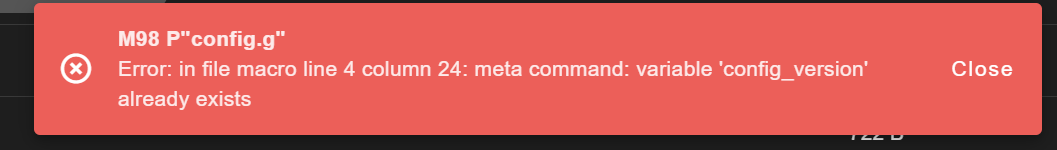
This is what I get when I try to do an M98
-
@Fickert That's cause by the 4th line of config.g:
global config_version = "Version 3.4.5 Config D"But only because it has already been created, at start up. If that's the only error message you get, it might be stopping running through config.g at that point, so won't report errors in your config.g.
Ian
Bed-slinger - Mini5+ WiFi/1LC | RRP Fisher v1 - D2 WiFi | Polargraph - D2 WiFi | TronXY X5S - 6HC/Roto | CNC router - 6HC | Tractus3D T1250 - D2 Eth
-
This post is deleted! -
I guess what is the purpose of doing a M98 P"config.g"? Just a proper way to print out the config and use in the forum?
on another note, my x axis upon start up is not triggered, but if I trigger it once with the endstop manager it remains triggered even if I push the gantry away from the endstops. Still making zero sense.
-
This post is deleted! -
This post is deleted! -
@Fickert said in Endstops Not triggering in Web GUI, but trigger LEDS on Duex:
I am currently assembling our new Big 60 V4 for work
Have you been in touch with Modix support yet?
-
@Herve_Smith
All of the endstops are Omron EE-SX4164-P2.
Checked the wiring to the sensor, it seems on par of whats in the datasheet and pinout of the duex.
M119 always shows "axis at min" regardless if its triggered or not. Even with the LEDS showing that it is registering them being triggered.
And sorry, never generally used M98 to post code on the forum. I tried to start doing such, but after the 5th attempt of ";" out things it kept asking for I gave up.
-
I did email them, but waiting for a response. I worry this is a defective Duex board (I swapped out the Duet Wifi for a spare I had sitting at home). Which that will not be fun.
Everything else seems to function flawlessly. All the macros for fans, leds, gantry movements, hotend, etc all work fine.
-
@Fickert Does your Duex follow the advice about the ground wire? https://docs.duet3d.com/Duet3D_hardware/Duet_2_family/DueX2_and_DueX5#power-wiring
Do not run separate ground wires from each terminal block back to the power supply unless the power supply is very close (less than 100mm) to the Duet 2 and DueX. Instead, run a very short and thick ground wire directly from the negative (-) terminal of the VIN terminal block on the DueX board to the negative VIN terminal of the Duet. Also connect the negative wire from your power supply to the negative VIN terminal of the Duet.
This is important, because otherwise you get grounding issues, as any potential difference between the Duet and Duex are grounded through small traces connected by the ribbon cable. Endstops are connected to ground.
Ian
Bed-slinger - Mini5+ WiFi/1LC | RRP Fisher v1 - D2 WiFi | Polargraph - D2 WiFi | TronXY X5S - 6HC/Roto | CNC router - 6HC | Tractus3D T1250 - D2 Eth
-
Yes, it is wired as described.
I finally did get the M98 print command to show I had "invalid number of visible axes". Changed the M584 P value to 3 instead of 4 (it should remain 4 due to the extruder right?) but still no change in homing issues.
-
To add confusion but yet some clarity of where to go next with this, I ended up swapping out the endstop on the y axis for a standard mechanical switch. Printer was able to home the y axis with me manually triggering the switch in my hand. What was odd though was that the endstop manager plugin still did not indicate it was working, but the m119 did. A lot of inconsistency going on. Hopefully this is just an endstop issue. In contact with Modix, and will see what they think of it.
-
So didn't get a response from Modix yet, but just a general update, the issue is solved. As pathetic as it sounds my 2a 3.3v - 5v fuse was bad. Had continuity but was failing under load.
Check your fuses kids.
-
@Fickert Great, glad you managed to resolve the problem.
Ian
-
 undefined Phaedrux marked this topic as a question
-
undefined Phaedrux has marked this topic as solved