Now that is customer support! Awesome!
Best posts made by Fickert
-
RE: Duet 2 Wifi magic smokeposted in Duet Hardware and wiring
-
RE: Endstops Not triggering in Web GUI, but trigger LEDS on Duexposted in Duet Hardware and wiring
So didn't get a response from Modix yet, but just a general update, the issue is solved. As pathetic as it sounds my 2a 3.3v - 5v fuse was bad. Had continuity but was failing under load.
Check your fuses kids.
-
RE: New CoreXY 400x400x560mm Build in Progressposted in My Duet controlled machine
@fcwilt said in New CoreXY 400x400x560mm Build in Progress:
@fickert said in New CoreXY 400x400x560mm Build in Progress:
I haven't had the chance to check the flatness on our granite block at work. Will look into that tomorrow.
That would be interesting.
Frederick
Just an update Frederick,
was able to check the flatness of the plate on our granite. About the flattest possible surface to check on (hence it was 30k for us to get made) and attached are my results with our feeler gauges.
from my findings, it looks like the flatness tolerance is between 0.10 - 0.15mm (0.10mm was slightly loose, and 0.15mm was snug) from each furthest corner. Considering thats spanning over 415mm square, I am very pleased with this tolerance. I am curious how close a sheet of glass would be to this.
Anywho, this helps me relieve that this is pretty darn flat
")


-
RE: Crane Quad review (Because it uses a Maestro)posted in General Discussion
Daniel I am glad I stumbled on your thread. What batch number were you?
I have to say I disagree with a majority of your review from what I have experienced (Sorry).
Quick summary of my experience:
I was Batch 4, for multiple reasons (Cheaper, and They worked out a lot of kinks between Batches 1-3) and I must say I was pleasantly surprised when mine arrived. Packaging was minimal unfortunately one mine, BUT I do packaging design at my workplace along side product design, and I felt a majority of the critical components were protected and fixtured enough for shipping. No real negatives there.
Out of the box I heard a rattling and found a screw had come loose on the inside holding the Duet Maestro to the printer frame. Easy fix.
As for the frame rigidity, I feel you got a bad unit or something because aside from me torquing the screws tighter for a snug fit, my frame is very solid. It wasn't perfectly square but didn't expect it to be, so I went about the assembly with a small square and straightened what I could, and re-adjusted all the cam bolts. Each wheel mates as it should with the extrusions, and no sheet metal parts are bent. As an Ender 3 Z-axis design (first time seeing one) its pretty solid. Very little slop when pulling only on the side without the leadscrew.
The Extruder is... interesting. Still trying to get it to work perfectly but only tried to print PETG on it so far. Feeding issues are hit and miss and random, which is very annoying. Still need to bite the bullet and order some PLA to really have fun with it and see if its just not meant to deal with PETG.
All in all, as far as a Kickstarter printer goes I am happy with it.
For the Maestro portion, it has performed flawless. No issues that have caused a concern, aside from some heater faults. Its actually nice to see some organization inside of the Systems tab. My CoreXY is a mess in comparison.
-
RE: Endstops Not triggering in Web GUI, but trigger LEDS on Duexposted in Duet Hardware and wiring
To add confusion but yet some clarity of where to go next with this, I ended up swapping out the endstop on the y axis for a standard mechanical switch. Printer was able to home the y axis with me manually triggering the switch in my hand. What was odd though was that the endstop manager plugin still did not indicate it was working, but the m119 did. A lot of inconsistency going on. Hopefully this is just an endstop issue. In contact with Modix, and will see what they think of it.
-
RE: New CoreXY 400x400x560mm Build in Progressposted in My Duet controlled machine


One thing I still really would like to do is mill and tap the joints at the ends and cut 45 degree 100-150mm extrusions for the corners.
-
Duet3 Incorporation with Roll2Roll Manufacturingposted in General Discussion
Hi guys,
So our development engineer has been tasked with adding a dispenser to our Roll2Roll line. Being experienced with hobbiest motion control outside of PLC he asked for my help. (I am not super familiar with PLC, neither is the engineer, so if were barking up the wrong tree please let us know).
In an essence, we will be adding a dispenser to travel across the Roll2Roll web (web direction will be -X, +X dispenser direction will be -Y, +Y), but we want to be able to link the dispenser speed with the line speed to assure the speed and dispensing rate will be adjusted to speed changes of the Roll2Roll line.
Our initial thoughts are to use Labview, but he is saying the stepper motor control incorporation is difficult to setup. Additionally I introduced a Duet3 into our large testing Cartesian robot so adding another seems tempting after I showed the ease of use and the quality of the board is.
Sorry for the rambling. To summarize, does this seem possible? Requirements we have found are:
- Control a single axis direction with a dispenser (Should work out the same as a CNC motion and spindle speed control for dispensing rate?)
- Take encoder information from Roll2Roll line, and adapt motion speed and dispensing rate.
- Expandable to possibly add an axis for a full X,Y direction.
Any suggestions would be greatly appreciated.
Thanks
-
New CoreXY 400x400x560mm Build in Progressposted in My Duet controlled machine
So as the title states I am in the works of building a design I have been working on for the past few months.
I first want to say I am typing this on a tablet so please bear with me if I have grammar errors.
Anywho, the start of this build was to convert my FT-5 to a corexy system but no design publically released addressed the issues I see in most corexy designs, Rigidity.
I also HATE the build plate platform design on the FT-5. Linear rods and bearings are used to keep it straight and flat, but fail doing so, as a matter of fact, I can tilt the bed with just light pressure on either the front or rear of the bed.
Lastly, I wanted a larger build area. 300 x 300 x 400 isn't enough, escpecially since the realistic build area I have found is 280 x 280mm.
The FT-5 did it right with using the mgn linear rails, and I am carrying that over to this design as well.

So Goals for this build:
-
Rigidity: Idler carriages and idler posts for the corexy system need to be solid. Will be solved with using aluminum square tubing and milled to size.
-
Lightweight: I want to create some inovation by making the gantry the lightest possible while being direct drive. Additionally, the idler carriages to also be light by using aluminum.
-
Bulletproof Build Platform: Having an unlevel build plate regardless of a BLTouch, is a pain. Aside from being level the build plate NEEDS to be repeatable.
-
Build Area: I wanted to get as close as possible to a TRUE 400mm x 400mm square size with at least a 500mm build height.
So to solve a these issues:
-
Rigidity: A lot of factors play into the rigidity of the design. One big factor is the aluminum tubing. Others are:
-
Aluminum is always going to beat any printed part in rigidity and weight.
-
Aluminumsquare tube will support the idler shafts for the bearings on both sides. A lot of designs only support the bearing shaft by one side, that can result in slop in belt tension during directional change.

-
Any printed part will be made from Carbon Fiber PC, which is a very rigid material; if you can print PC I highly recommend it for builds over ABS, PETG, Etc.

-
The frame is pretty similar to the FT-5, there are a few more extrusions but I think it will be plenty study, especially with using 90 degree cast aluminum braces and likely external braces.
-
-
Idler Bearing Size: I stumbled across an article from a builder that had a direct drive system printing at 150mm/s and higher https://drmrehorst.blogspot.com/2017/07/ummd-corexy-mechanism.html and he swore by using 608 bearings (dia of 22mm was optimal for skewing of the position of the head or something) so I wanted these to be used in the design.
*Can't remember now off the top of my head will get the link and post when I get to work tomorrow. -
Lightweight: When I say lightweight I mainly mean mainly the gantry, carriage idlers, and x-axis.
- Gantry: I am swapping to a nema 14 round stepper and a single 4010 blower fan (may opt for 2 fans, will test cooling after it is assembled), and the stepper motor alone shaves 100g from the standard nema 17 pancake stepper motor for the titan aero.

- I opted for a MGN9N rail for the x-axis. This shaves off a fair amount of weight to throw back and forth on the y-axis. I do have concern of harmonics on the rail at high speeds but there isn't a really good way to check this until its up and running.[link text](link url)
- Gantry: I am swapping to a nema 14 round stepper and a single 4010 blower fan (may opt for 2 fans, will test cooling after it is assembled), and the stepper motor alone shaves 100g from the standard nema 17 pancake stepper motor for the titan aero.
-
Bulletproof Build Platform: I mentioned the FT-5 build platform in my opinion is garbage. There are quite a few key features in my build plate design that I feel will make this rock solid:
- The base will be made of 2020 aluminum extrusion with 90 degree cast aluminum corner braces and Carbon Fiber PC braces for flatness and rigidity.
- Linear motion will be guided by two 600mm MGN 12 rails, which GREATLY reduce the slop the stock bed has in the FT-5.
The photo below does not have the lead screws in yet but you can see the three supports off the bed platform.


- There will be 3 Leadscrews to fully fix this build plane, and these will all be tied to a single stepper motor.
- The build plate I splurged on a bit. I ended up buying a 1/4in thick 6061 aluminum plate measuring 415mm x 415mm. The plate has been ground with a flatness tolerance of +- 0.38mm. Should be pretty good even if I decide to not use glass.


-
Build Area: The build area was a huge "Gotta have" thing for this build to help drive keeping everything to be at the absolute maxed position to keep clear from the gantry. My main focus like I stated was the square flat area of 400mm x 400mm, while having a direct drive extruder. To achieve this, I eliminated the BL Touch and will be using stall homing (on all axis actually) as well as a change in stepper motor. The round Nema 14 stepper motor's lightweight is one large positive, but its form factor was the other. The total footprint of the nema14 stepper and the 4010 fan are smaller in depth than the nema 17 pancake stepper, and still in the same 40mm x 40mm form factor.

Electronics: Obviously this will be using the Duet Wifi, but additionaly it will have all the following:
-
Controller: Duet Wifi
-
PSU: MeanWell SE24 600Watt
-
Stepper Motors: Standard nema17 stepper motors from the FT-5
-
Heat Bed: 120V AC 1000W 400mm x 400mm silcone bed heater controlled by a SSR with heatsink
-
Extruder: E3D Titan Aero; not sure if I will be using the volcano or v6 hotend yet.
Still to do:
I still have to design a few parts yet, but with my parts coming in the mail and seeing my frame take shape I wanted to start to document the build for others.

-
Latest posts made by Fickert
-
RE: Endstops Not triggering in Web GUI, but trigger LEDS on Duexposted in Duet Hardware and wiring
So didn't get a response from Modix yet, but just a general update, the issue is solved. As pathetic as it sounds my 2a 3.3v - 5v fuse was bad. Had continuity but was failing under load.
Check your fuses kids.
-
RE: Endstops Not triggering in Web GUI, but trigger LEDS on Duexposted in Duet Hardware and wiring
To add confusion but yet some clarity of where to go next with this, I ended up swapping out the endstop on the y axis for a standard mechanical switch. Printer was able to home the y axis with me manually triggering the switch in my hand. What was odd though was that the endstop manager plugin still did not indicate it was working, but the m119 did. A lot of inconsistency going on. Hopefully this is just an endstop issue. In contact with Modix, and will see what they think of it.
-
RE: Endstops Not triggering in Web GUI, but trigger LEDS on Duexposted in Duet Hardware and wiring
Yes, it is wired as described.
I finally did get the M98 print command to show I had "invalid number of visible axes". Changed the M584 P value to 3 instead of 4 (it should remain 4 due to the extruder right?) but still no change in homing issues.
-
RE: Endstops Not triggering in Web GUI, but trigger LEDS on Duexposted in Duet Hardware and wiring
I did email them, but waiting for a response. I worry this is a defective Duex board (I swapped out the Duet Wifi for a spare I had sitting at home). Which that will not be fun.
Everything else seems to function flawlessly. All the macros for fans, leds, gantry movements, hotend, etc all work fine.
-
RE: Endstops Not triggering in Web GUI, but trigger LEDS on Duexposted in Duet Hardware and wiring
@Herve_Smith
All of the endstops are Omron EE-SX4164-P2.
Checked the wiring to the sensor, it seems on par of whats in the datasheet and pinout of the duex.
M119 always shows "axis at min" regardless if its triggered or not. Even with the LEDS showing that it is registering them being triggered.
And sorry, never generally used M98 to post code on the forum. I tried to start doing such, but after the 5th attempt of ";" out things it kept asking for I gave up.
-
RE: Endstops Not triggering in Web GUI, but trigger LEDS on Duexposted in Duet Hardware and wiring
I guess what is the purpose of doing a M98 P"config.g"? Just a proper way to print out the config and use in the forum?
on another note, my x axis upon start up is not triggered, but if I trigger it once with the endstop manager it remains triggered even if I push the gantry away from the endstops. Still making zero sense.
-
RE: Endstops Not triggering in Web GUI, but trigger LEDS on Duexposted in Duet Hardware and wiring
@droftarts said in Endstops Not triggering in Web GUI, but trigger LEDS on Duex:
M98 P"config.g"
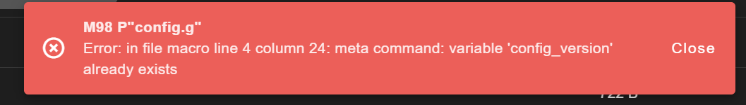
This is what I get when I try to do an M98
-
RE: Endstops Not triggering in Web GUI, but trigger LEDS on Duexposted in Duet Hardware and wiring
Hey Ian, so the X0:1 Y:5 was my mistake, I was just trying stuff to see what would work. That was not the issue. Sorry to add the confusion.
Ignoring my mistake, none of the estops function properly. I also tried "exp.e5stop" by getting the reference from the RRF config tool, but still no luck.
Also for some reason M98 P"config.g" did not work for me when I attempted it in the console.
-
Endstops Not triggering in Web GUI, but trigger LEDS on Duexposted in Duet Hardware and wiring
As the title states, I am currently assembling our new Big 60 V4 for work, and have an odd endstop issue. Using the configuration for the Big 60 provided, none of the end stops trigger in the Web GUI, but on the Duex expansion board, the appropriate leds trigger on and off.
They are using optical sensors.
Any help would be greatly appreciated.
Config and M122 below:
; Modix Big-60 V4, Duex Expansion, IDEX single extruder
; Configuration file for Duet WiFi (firmware version 3.4.5)
; Generated by Modix - Version 3.4.5 Config D
global config_version = "Version 3.4.5 Config D"
global generation = 4 											; generation 4 printer
global printhead  = 1 											; Griffin printhead
global printheads = 1											; dual extruder
global expansion = 1 											; Duex expansion board is installed
global idex = 0													; idex setup
; for macro commands
global pausetime = 0											; record pauzing time
global fan_0_speed = 0 											; Used to store the fan0 speed
global fan_1_speed = 0 											; Used to store the fan1 speed
global filamentswitch = 0 										; filament switch disabled (edited)
global changer_count = 0 										; Counter for tool changer continous.
global toolstate = 0											; used for pauses

; General preferences_________________________________________________________
G90																; send absolute coordinates...
M83																; ...but relative extruder moves
M555 P2															; Set output to look like Marlin
M575 P1 B57600 S1												; Set auxiliary serial port baud rate and require checksum (for PanelDue)

; Network_____________________________________________________________________
M550 P"Big 60 V4"												; set printer name
;M551 P"MODIX3D"												; Set password (optional)
M98 P"config_networking.g"										; enable network
;M552 P0.0.0.0													; Uncomment this command for using Duet Ethernet board
G4 P300															; wait 300ms

; Drives_________________________________________________________________________
;Main board______________________________________________________________________
M569 P0 S1														; Physical drive 0. X-B-M
M569 P1 S0														; Physical drive 1. X-F-M
M569 P2 R-1														; Physical drive 2. U Secondary
M569 P3 S1                                                  	; Physical drive 3. E0-Extruder.
M569 P4 S0                                                 		; Physical drive 4. E1-Extruder.
;Duex5 board_____________________________________________________________________
M569 P5 S0														; Physical drive 5. Y
M569 P6 S1														; Physical drive 6. Z-Back-Left (ZBL)
M569 P7 S1														; Physical drive 7. Z-Front-Left (ZFL)
M569 P8 S1														; Physical drive 8. Z-Front-Right (ZFR)
M569 P9 S1														; Physical drive 9. Z-Back-Right (ZBR)

;Settings_________________________________________________________
M584 X0:1 Y5 Z6:7:8:9 E3:4 P4									; Driver mapping
M671 X-185:-185:668:668 Y668:-46:-46:668 S30    				; Anticlockwise
;___________________________________________________________________
M350 X16 Y16 Z16 E16:16 I1										; Configure microstepping with interpolation
M92 X80 Y80 Z2000 E400:400										; Set steps per mm
M566 X500 Y500 Z30 E3000:3000 P1 								; Set maximum instantaneous speed changes (mm/min)
M203 X18000 Y18000 Z400 E6000:6000 								; Set maximum speeds (mm/min)
M201 X3000 Y3000 Z240 E1000:1000 								; Set accelerations (mm/s^2)
M204 P1000 T3000 												; Set print and travel accelerations  (mm/s^2)
M906 X1800 Y1800 Z1800 E1000:1000 I50							; Set motor currents (mA) and motor idle factor in per cent
M84 S100														; Set idle timeout - 100 seconds

; Axis Limits
M208 X0 Y0 Z-2 S1                               				; set axis minima
M208 X600 Y600 Z1200 S0											; set axis maxima

; Endstops
M574 X1 S1 P"duex.e5stop + duex.e6stop"							; configure switch-type (e.g. microswitch) endstop for low end on X via pin e5stop + e6stop
M574 Y1 S1 P"duex.e4stop"										; configure switch-type (e.g. microswitch) endstop for low end on Y via pin e4stop
; Automatic Z Offset Calibration____________________________________
M574 Z1 S1 P"!duex.e2stop"										; configure switch-type for Automatic z-offset

; Z-Probe
M558 P9 C"zprobe.in" H3 F180 T12000 A1 R0.5						; BLTouch probing settings
M950 S0 C"duex.pwm5"											; sets the BLTouch probe
M376 H100			                							; Height (mm) over which to taper off the bed compensation
G31 P500 X0 Y32.4												; BLTouch X and Y offset
M557 X{move.axes[0].min + sensors.probes[0].offsets[0] + 1, move.axes[0].max + sensors.probes[0].offsets[0] - 1} Y{move.axes[1].min + sensors.probes[0].offsets[1] + 1, move.axes[1].max + sensors.probes[0].offsets[1] - 1} P10:10
																; The M557 is used to define the mesh grid area. It uses the P parameter to set the amount of probing points. P10:10 would be a 10x10 grid. Supports up to a 441 point grid.
M98 P"config_probe.g"											; Load the Z-offset from the config_probe.g file
																; The Z_offset value is now set in config_probe.g, not in config.g
																; Adjust the values there, do not adjust anything here.

; Heaters___________________________________________________________
M140 H-1                                       					; disable heated bed (overrides default heater mapping)

;E0_________________________________________________________________
;M308 S0 P"e0temp" Y"thermistor" T100000 B4725   				; configure sensor 0 as thermistor on pin e0temp
;M308 S0 P"spi.cs1" Y"rtd-max31865"								; Configure sensor 0 as PT100 via the daughterboard
M308 S0 P"e0temp" Y"pt1000"										; Configure sensor 0 as PT1000 on pin e0temp
M950 H0 C"e0heat" T0                            				; create nozzle heater output on e0heat and map it to sensor 0
M98 P"PID_tune_E0.g" R1											; PID calibration
M143 H0 S300                                    				; set temperature limit for heater 0 to 285C

; Fans______________________________________________________________
M950 F0 C"fan0" Q500                            				; create fan 0 on pin fan0 and set its frequency
M106 P0 S0 H-1 C"Primary blower fan"							; set fan 0 value. Thermostatic control is turned on
M950 F3 C"duex.fan5" Q500                       				; create fan 3 on pin fan5 and set its frequency
M106 P3 S255 H0 T45                             				; set fan 3 value. Thermostatic control is turned on
; LED______________________________________________________________
M950 F2 C"duex.fan7" Q500                            			; create LED on pin fan7 and set its frequency
M106 P2 S0 H-1 C"LED Primary"                            		; Disable fan channel for LED
M950 F5 C"duex.fan8" Q500                            			; create LED ENC on pin fan8 and set its frequency
M106 P5 S0 H-1 C"LED ENC"                              			; Disable fan channel for LED
M106 P5 S255													; Enclosure LED on by default
M106 P2 S255													; Primary LED on by default

; Tools______________________________________________________________
;T0_________________________________________________________________
M563 P0 S"E0 Primary" D0 H0 F0 	                				; define tool 0
G10 P0 X0 Y0 Z0                                 				; set tool 0 axis offsets
G10 P0 S210 R180                                  				; set initial tool 0 active and standby temperatures to 210 and 180c by default

; Automatic power saving____________________________________________
M911 S22.0 R23.5 P"M913 X0 Y0 G91 M83 G1 Z3 E-5 F1000"   	  	; Set voltage thresholds and actions to run on power loss. Power Failure Pause

; Primary hotend Clog detector__________________________________________________
M591 D0 P7 C"e0stop" S1 L3.14 E10 R10:300						; Clog Detector E0 [Add-On]

; Crash detector__________________________________________________
M950 J2 C"zstop" 												; create Input Pin 2 on pin E4 to for M581 Command.
;M581 P2 T0 S0 R0												; Crash Detector   [Add-On]

; Emergency stop button__________________________________________________
M950 J3 C"ystop" 												; create Input Pin 3 on pin ystop to for M581 Command.
M950 J4 C"xstop" 												; create Input Pin 4 on pin xstop to for M581 Command.
M581 P3 T0 S1 R0 												; Emergency stop [Add-On]
;M581 P4 T0 S1 R0												; Emergency stop [Add-On]

;M501
m122 === Diagnostics === RepRapFirmware for Duet 2 WiFi/Ethernet version 3.4.5 (2022-11-30 19:36:12) running on Duet WiFi 1.02 or later + DueX5v0.11 Board ID: 0JD0M-9P6M2-NW4SD-6JKDG-3SJ6L-KAQMK Used output buffers: 1 of 26 (18 max) === RTOS === Static ram: 23836 Dynamic ram: 76156 of which 0 recycled Never used RAM 9232, free system stack 182 words Tasks: NETWORK(notifyWait,13.5%,237) HEAT(notifyWait,0.0%,333) Move(notifyWait,0.0%,363) DUEX(notifyWait,0.0%,24) MAIN(running,86.3%,438) IDLE(ready,0.2%,30), total 100.0% Owned mutexes: WiFi(NETWORK) === Platform === Last reset 00:08:52 ago, cause: software Last software reset at 2023-08-14 09:11, reason: User, GCodes spinning, available RAM 8980, slot 0 Software reset code 0x0003 HFSR 0x00000000 CFSR 0x00000000 ICSR 0x0041f000 BFAR 0xe000ed38 SP 0x00000000 Task MAIN Freestk 0 n/a Error status: 0x00 Aux0 errors 0,0,0 Step timer max interval 0 MCU temperature: min 33.3, current 34.3, max 34.8 Supply voltage: min 24.1, current 24.3, max 24.7, under voltage events: 0, over voltage events: 0, power good: yes Heap OK, handles allocated/used 99/14, heap memory allocated/used/recyclable 2048/208/4, gc cycles 0 Events: 0 queued, 0 completed Driver 0: standstill, SG min n/a Driver 1: standstill, SG min n/a Driver 2: standstill, SG min n/a Driver 3: standstill, SG min n/a Driver 4: standstill, SG min n/a Driver 5: standstill, SG min n/a Driver 6: standstill, SG min n/a Driver 7: standstill, SG min n/a Driver 8: standstill, SG min n/a Driver 9: standstill, SG min n/a Driver 10: Driver 11: Date/time: 2023-08-14 09:20:46 Cache data hit count 4294967295 Slowest loop: 12.18ms; fastest: 0.19ms I2C nak errors 0, send timeouts 0, receive timeouts 0, finishTimeouts 0, resets 0 === Storage === Free file entries: 10 SD card 0 detected, interface speed: 20.0MBytes/sec SD card longest read time 0.5ms, write time 2.5ms, max retries 0 === Move === DMs created 83, segments created 0, maxWait 0ms, bed compensation in use: none, comp offset 0.000 === MainDDARing === Scheduled moves 0, completed 0, hiccups 0, stepErrors 0, LaErrors 0, Underruns [0, 0, 0], CDDA state -1 === AuxDDARing === Scheduled moves 0, completed 0, hiccups 0, stepErrors 0, LaErrors 0, Underruns [0, 0, 0], CDDA state -1 === Heat === Bed heaters -1 -1 -1 -1, chamber heaters -1 -1 -1 -1, ordering errs 0 === GCodes === Segments left: 0 Movement lock held by null HTTP is idle in state(s) 0 Telnet is idle in state(s) 0 File is idle in state(s) 0 USB is idle in state(s) 0 Aux is idle in state(s) 0 Trigger is idle in state(s) 0 Queue is idle in state(s) 0 LCD is idle in state(s) 0 Daemon is idle in state(s) 0 Autopause is idle in state(s) 0 Code queue is empty === Filament sensors === Extruder 0 sensor: no data received === DueX === Read count 1, 0.11 reads/min === Network === Slowest loop: 38.52ms; fastest: 0.00ms Responder states: HTTP(0) HTTP(0) HTTP(0) HTTP(0) FTP(0) Telnet(0) HTTP sessions: 1 of 8 = WiFi = Network state is active WiFi module is connected to access point Failed messages: pending 0, notready 0, noresp 0 WiFi firmware version 1.27 WiFi MAC address c8:c9:a3:40:13:bb WiFi Vcc 3.45, reset reason Power up WiFi flash size 2097152, free heap 25288 WiFi IP address 192.168.237.66 WiFi signal strength -61dBm, mode 802.11n, reconnections 0, sleep mode modem Clock register 00002002 Socket states: 0 0 0 0 0 0 0 0 -
RE: CoreXY vibration and noise at specific speedsposted in Tuning and tweaking
@matt3o Sorry to bring up an old post, but did you ever find the solution to this? I also have similar noise issues and curious if you found a culprit.