Nozzle detach the part - Chiron Duet 2 wifi
-
This post is deleted! -
@droftarts the following as requested:
- config.g
; Configuration file for Duet WiFi (firmware version 3.3)
; executed by the firmware on start-up
;
; generated by RepRapFirmware Configuration Tool v3.3.16 on Fri Aug 04 2023 19:59:42 GMT+0200 (Ora legale dell’Europa centrale)
; General preferences
M575 P1 S1 B57600 ; enable support for PanelDue
G90 ; send absolute coordinates...
M83 ; ...but relative extruder moves
M550 P"Chiron" ; set printer name; Network
M552 S1 ; enable network
M586 P0 S1 ; enable HTTP
M586 P1 S0 ; disable FTP
M586 P2 S0 ; disable Telnet; Drives
M569 P0 S0 ; physical drive 0 goes backwards
M569 P1 S0 ; physical drive 1 goes backwards
M569 P2 S0 ; physical drive 2 goes backwards
M569 P3 S1 ; physical drive 3 goes forwards
M569 P4 S0 ; physical drive 4 goes backwards
M584 X0 Y1 Z2:4 E3 ; set drive mapping
M350 X16 Y16 Z16 E16 I1 ; configure microstepping with interpolation
M92 X80.00 Y100.00 Z400.00 E420.00 ; set steps per mm
M566 X900.00 Y900.00 Z60.00 E120.00 ; set maximum instantaneous speed changes (mm/min)
M203 X6000.00 Y6000.00 Z180.00 E1200.00 ; set maximum speeds (mm/min)
M201 X500.00 Y500.00 Z20.00 E250.00 ; set accelerations (mm/s^2)
M906 X1000 Y1000 Z1000 E900 I30 ; set motor currents (mA) and motor idle factor in per cent
M84 S0 ; Disable motor idle current reduction; Axis Limits
M208 X-15 Y-15 Z0 S1 ; set axis minima
M208 X400 Y400 Z440 S0 ; set axis maxima; Endstops
M574 X1 S1 P"!xstop" ; configure switch-type (e.g. microswitch) endstop for low end on X via pin xstop
M574 Y1 S1 P"!ystop" ; configure switch-type (e.g. microswitch) endstop for low end on Y via pin ystop
M574 Z1 S1 P"zstop+e1stop" ; configure active-high endstop for low end on Z via pin zstop and e1stop; Z-Probe
M558 P0 H5 F120 T6000 ; disable Z probe but set dive height, probe speed and travel speed
M557 X15:385 Y15:385 S60 ; define mesh grid; Heaters
M308 S0 P"bedtemp" Y"thermistor" T100000 B4138 ; configure sensor 0 as thermistor on pin bedtemp
M950 H0 C"bedheat" T0 ; create bed heater output on bedheat and map it to sensor 0
M307 H0 B0 S1.00 ; disable bang-bang mode for the bed heater and set PWM limit
M140 H0 ; map heated bed to heater 0
M143 H0 S120 ; set temperature limit for heater 0 to 120C
M308 S1 P"e0temp" Y"thermistor" T100000 B4138 ; configure sensor 1 as thermistor on pin e0temp
M950 H1 C"e0heat" T1 ; create nozzle heater output on e0heat and map it to sensor 1
M307 H1 B0 S1.00 ; disable bang-bang mode for heater and set PWM limit
M143 H1 S285 ; set temperature limit for heater 1 to 285C; Fans
M950 F0 C"fan0" Q500 ; create fan 0 on pin fan0 and set its frequency
M106 P0 S0 H-1 ; set fan 0 value. Thermostatic control is turned off
M950 F1 C"fan1" Q500 ; create fan 1 on pin fan1 and set its frequency
M106 P1 S1 H1 T45 ; set fan 1 value. Thermostatic control is turned on; Tools
M563 P0 D0 H1 F0 ; define tool 0
G10 P0 X0 Y0 Z0 ; set tool 0 axis offsets
G10 P0 R0 S0 ; set initial tool 0 active and standby temperatures to 0C; Custom settings are not defined
; Miscellaneous
M501 ; load saved parameters from non-volatile memory
M911 S10 R11 P"M913 X0 Y0 G91 M83 G1 Z3 E-5 F1000" ; set voltage thresholds and actions to run on power loss- M115
FIRMWARE_NAME: RepRapFirmware for Duet 2 WiFi/Ethernet FIRMWARE_VERSION: 3.4.6 ELECTRONICS: Duet WiFi 1.02 or later FIRMWARE_DATE: 2023-07-21 14:08:28
- config.g
-
@droftarts said in Nozzle detach the part - Chiron Duet 2 wifi:
Does this happen on all prints?
The over-extrusion is caused by the parameter "Initial Layer Flow" set to 110%
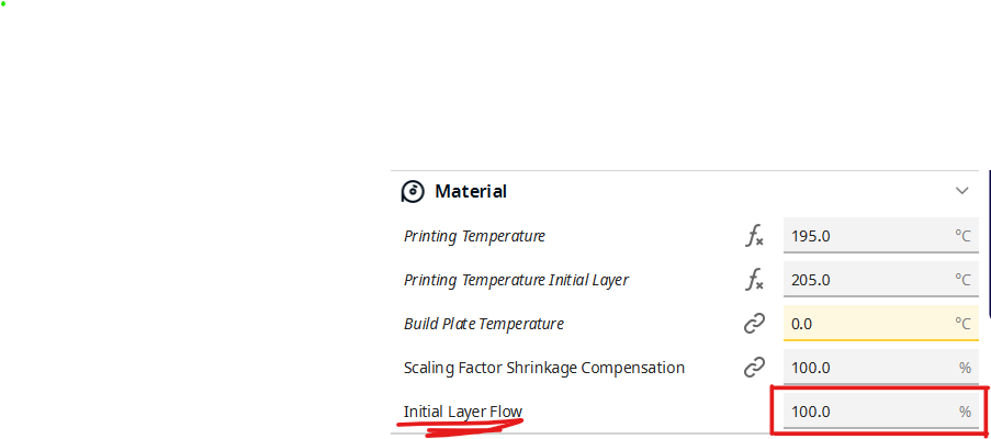
With that parameter reset to 100% this is what happens
Basically the same problem with the actual settings. I inform the now the bed level was set strait to the nozzle, between 0.09-0.05 mm. Instead when the bed level was set wider let's say between 0.13-0.09 mm the part comes off on its own, starting from the borders like the warping effect. But I don't know if this happened because the filament cannot cling to the surface or is always caused by the nozzle.
-
@Phaedrux I do that check with the ruler and I'm pretty sure that the z-axis moves correctly.
-
@Herve_Smith said in Nozzle detach the part - Chiron Duet 2 wifi:
era l'unica cosa che potevo trovare per risolvere il problema
based on what can I understand that the problem is caused by the motors?
-
@droftarts said in Nozzle detach the part - Chiron Duet 2 wifi:
il gcode che causa il problema
-
This post is deleted! -
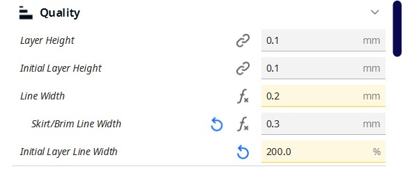
@genioluiz7 It looks from your gcode file that you are printing 0.1mm layer height, and that the line width is 0.2mm. This sounds very small, and probably doesn't suit your nozzle; I think the Chiron comes with a 0.4mm nozzle. So I think there are some issues with the settings you have chosen in Cura. Can you post a picture of the settings you are using?
Looking at your config.g, I think your maximum instantaneous speed change (aka jerk) M566 Z value is too high for a Z leadscrew system. 60mm/min = 1mm/sec, and it may be that short Z moves don't complete properly due to inertia on the Z axis. Try reducing M566 Z to 10, by changing the following line in the '; Drives' section of your config.g:
M566 X900.00 Y900.00 Z10.00 E120.00 ; set maximum instantaneous speed changes (mm/min)Maximum speed (M203) and Acceleration (M201) look about right to me.
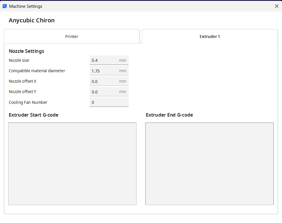
If that doesn't help, check that the filament diameter is set correctly for the filament you are using, in Settings > Printer > Manage printers, then select your printer from the list and click 'Machine settings', then check the filament diameter on the 'Extruder 1' tab. Nozzle Settings > Compatible material diameter should match the filament diameter you are using.
Finally, have you calibrated the extruder? See https://docs.duet3d.com/en/How_to_guides/Calibration#h-3-calibrating-extruder-e-steps-per-mm
Ian
Bed-slinger - Mini5+ WiFi/1LC | RRP Fisher v1 - D2 WiFi | Polargraph - D2 WiFi | TronXY X5S - 6HC/Roto | CNC router - 6HC | Tractus3D T1250 - D2 Eth
-
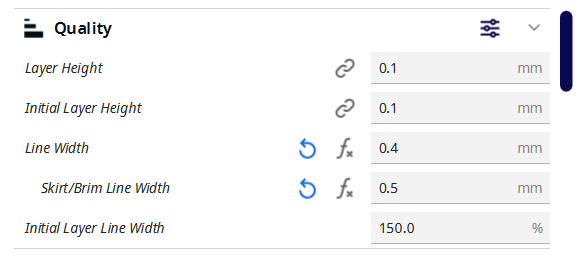
@droftarts you're completely right.
Do you want to see only the "quality" parameters? Or all the other too?
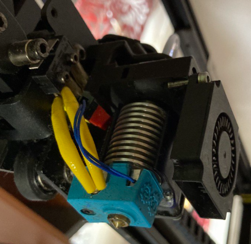
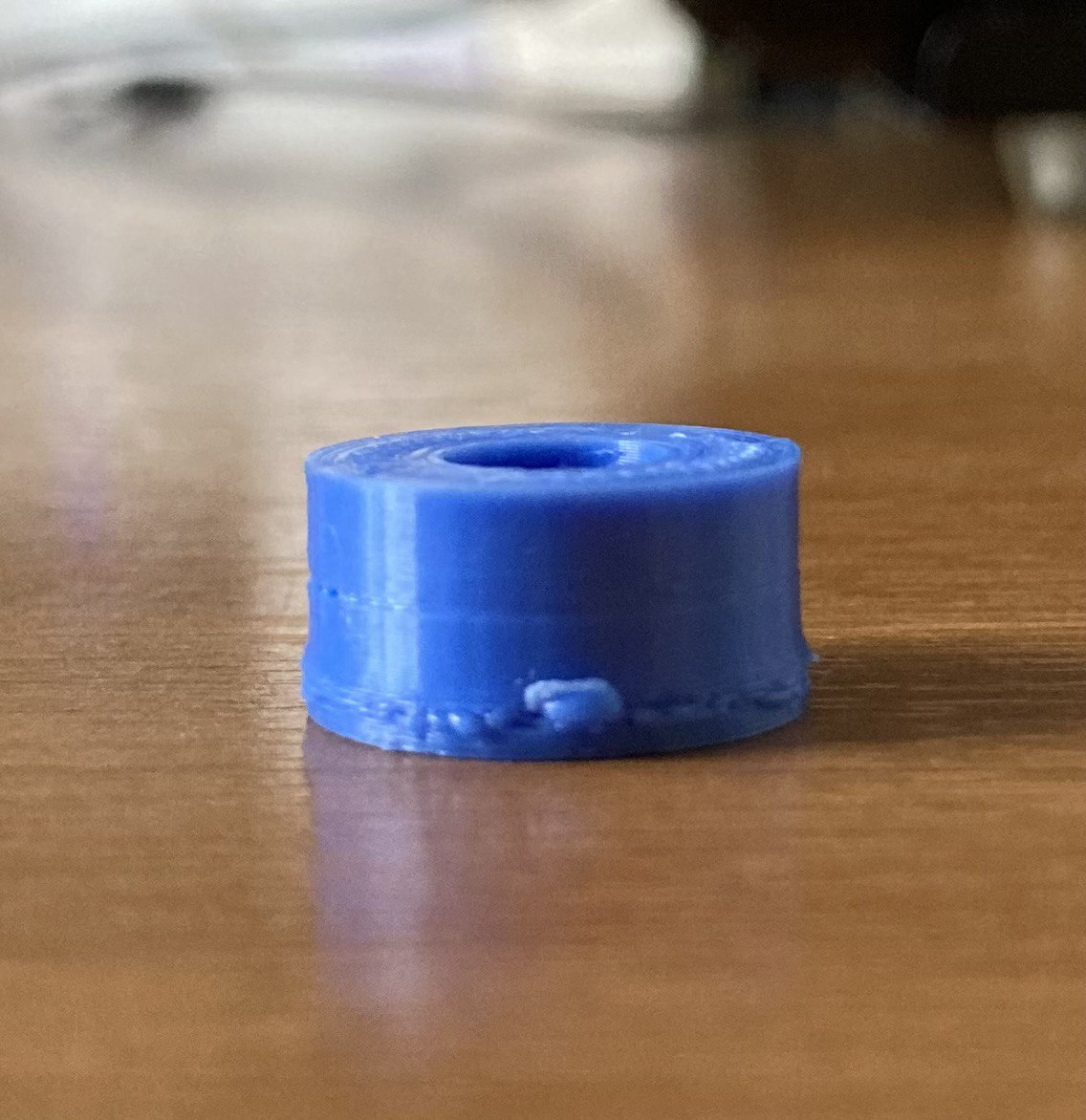
![be9e55a0-b766-49be-9fc5-a4ab2800dd4d-image.png]This is the nozzle I'm using. It's 0.4 mm, as you presaid.
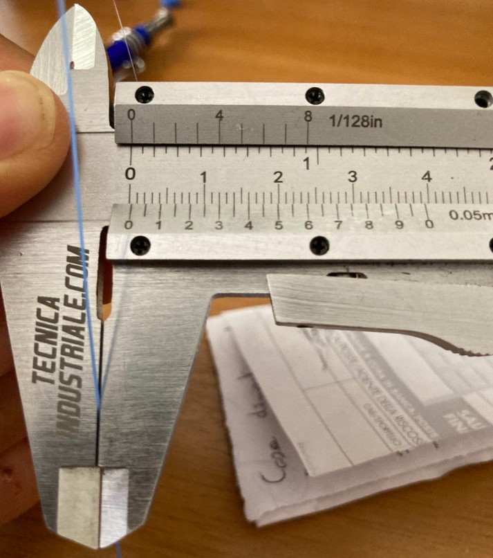
I mesured the width of the extruded filament and is more or less 0.4 mm as you can see in the picture below
Have you calibrated the extruder? Unfortunately not yet. I start now. And I'll let you know the results.
-
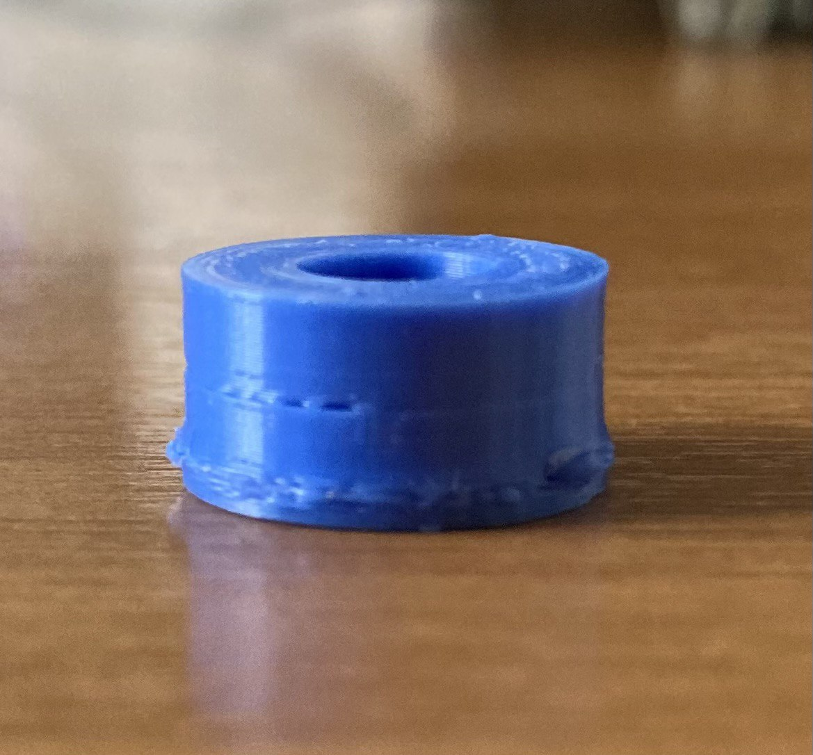
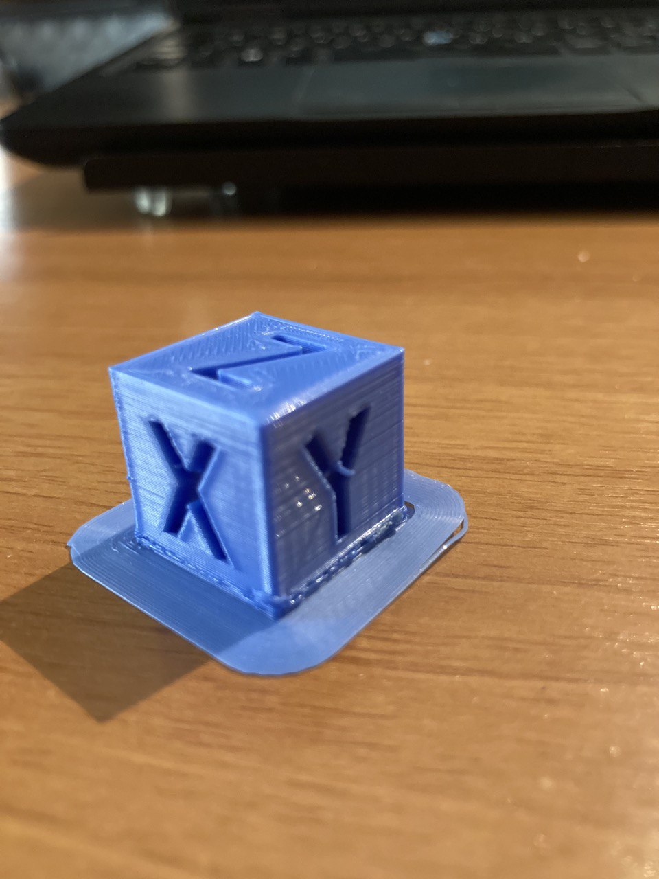
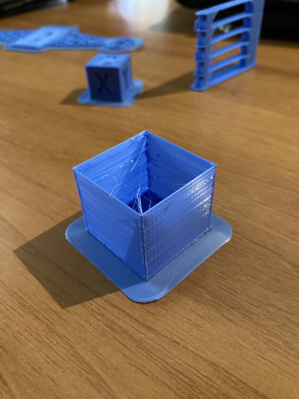
@genioluiz7
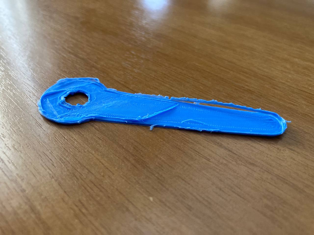
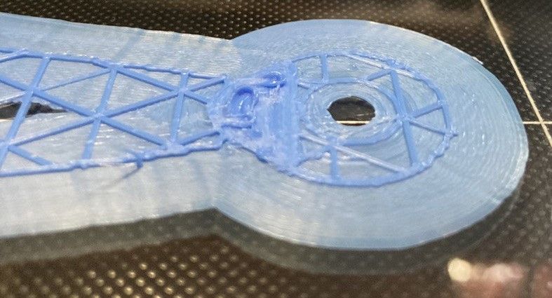
I've just tried to print something easy and the resut was amazing. Really better compared to the last one. But I can see that the bottom of the part is widther compared to the rest of it. What do you think?
-
@genioluiz7 Did you change the M566 line? Did that help?
With the line width, you generally don't go thinner than your nozzle diameter. Check that your nozzle diameter is set to 0.4 in in Settings > Printer > Manage printers > Machine settings > Extruder 1tab > Nozzle Settings > Nozzle size
Ian
Bed-slinger - Mini5+ WiFi/1LC | RRP Fisher v1 - D2 WiFi | Polargraph - D2 WiFi | TronXY X5S - 6HC/Roto | CNC router - 6HC | Tractus3D T1250 - D2 Eth
-
@genioluiz7 It looks like the nozzle may be a bit low on the initial layer height, along with some extrusion issues (possibly retraction) and over-extrusion. It looks like there's something going on at the point where it changes from solid layers to infill layers.
0.1mm layers are about as low as you can go, and causes other problems, especially with overhangs and bridging. It might be worth starting with a higher layer height (eg 0.2 or 0.3) to get things working well, before reducing the layer height.
Ian
-
-
@genioluiz7 That looks okay. I think it's just tuning your Cura profile, and tuning the printer for speed, acceleration, retraction, pressure advance, etc etc... . Follow the Calibration section here https://docs.duet3d.com/en/How_to_guides/Calibration, or Teaching Techs more exhaustive guide here:https://teachingtechyt.github.io/calibration.html#intro
Ian
Bed-slinger - Mini5+ WiFi/1LC | RRP Fisher v1 - D2 WiFi | Polargraph - D2 WiFi | TronXY X5S - 6HC/Roto | CNC router - 6HC | Tractus3D T1250 - D2 Eth
-
@genioluiz7 said in Nozzle detach the part - Chiron Duet 2 wifi:
@Herve_Smith said in Nozzle detach the part - Chiron Duet 2 wifi:
era l'unica cosa che potevo trovare per risolvere il problema
based on what can I understand that the problem is caused by the motors?
Does it have 2 Z motors? Is there a model number on them? Are they connected to the two Z motor outputs of the Duet 2?
Duet 2 has the two Z motor connectors wired in series. That's generally the best arrangement if the Z motors are similar to the XY motors. However, after Duet 2 was released some printer manufacturers started using low current high inductance Z motors that they intended to be connected in parallel. If your machine has that type of motor, then the series connection will reduce the maximum Z speed that can safely be used.
Duet WiFi hardware designer and firmware engineer
Please do not ask me for Duet support via PM or email, use the forum
http://www.escher3d.com, https://miscsolutions.wordpress.com -
@dc42 this is the actual configuration:
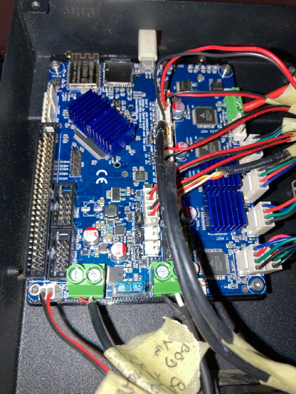
The 2 calbes connected bottom right.Following the pictures of the z motor
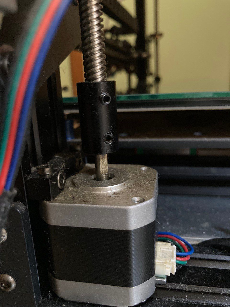
and of the x motor
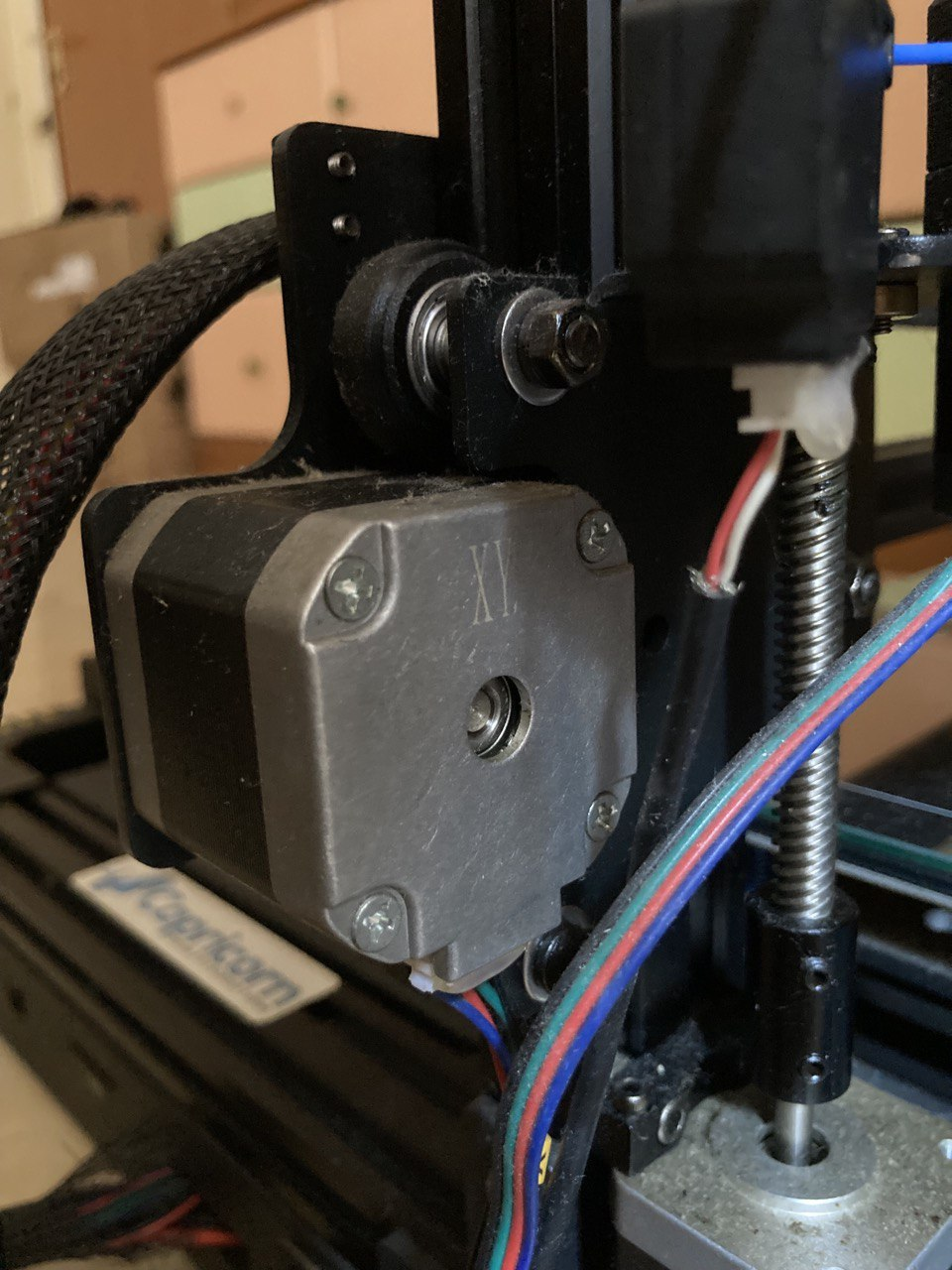
They seem the same.
Let me know what you think?
-
@genioluiz7 if you have a multimeter then you could unplug the X and Z motors from the Duet and measure the resistances of one phase of each.
Duet WiFi hardware designer and firmware engineer
Please do not ask me for Duet support via PM or email, use the forum
http://www.escher3d.com, https://miscsolutions.wordpress.com -
@dc42 Where have I to put the positive and the negative tips? Can you describe it more precisely?
-
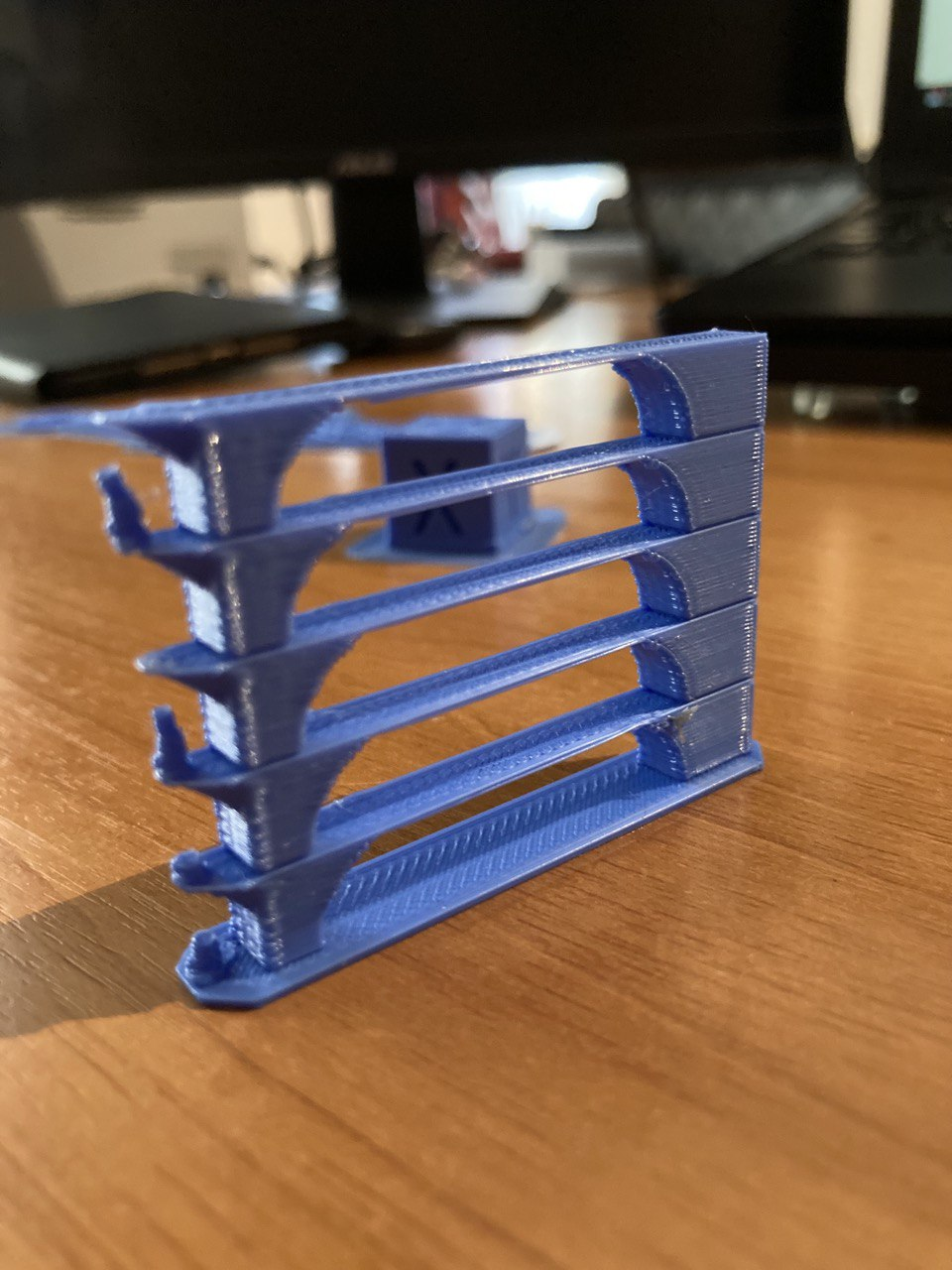
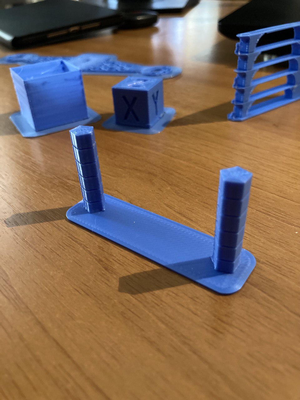
I follow the Teaching Techs guide here:https://teachingtechyt.github.io/calibration.html#intro (This one not jet
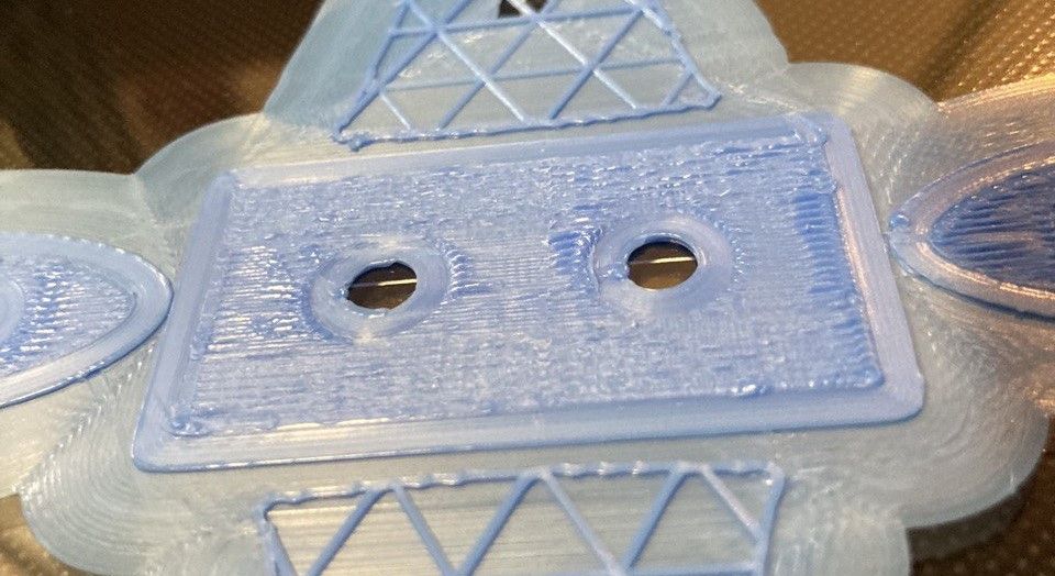
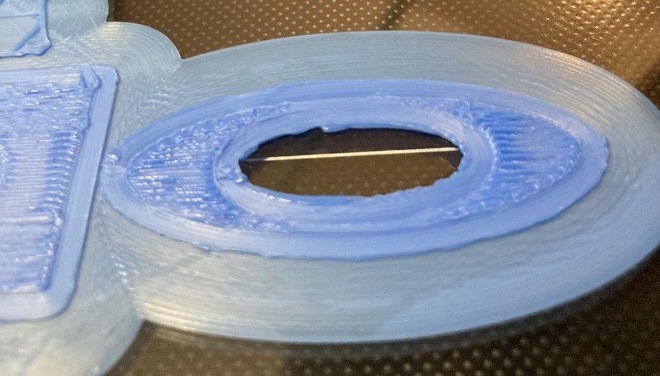
https://docs.duet3d.com/en/How_to_guides/Calibration ) and the tests are all good.Now I'm printing something bigger and this what is happening:
This is the g.code I'm using https://we.tl/t-33Er3mvoe0
What do you think? Is that a problem of speed, temperature, cooling, retraction or adhesion?To be more coplete I post also the picture of the tests
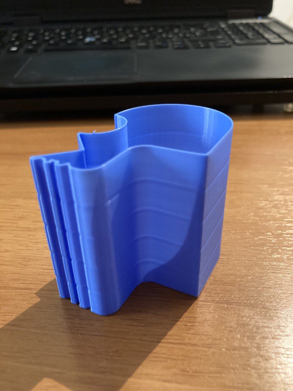
-
It still looks like over extrusion to me. Try reducing the extrusion factor to 90 or 95% and see if it helps.