Duet3 Mini5+ Ethernet Nozzle Distance to PEI sheet is too large
-
@Wobi Change the Q parameter in this line:
M950 E0 C"led" T2 Q800000back to Q3000000. I've found that my LEDs don't work correctly with Q800000. I mistakenly thought Q was the bits per second rate, but it is the SPI clock frequency, which is 4x the bit rate, hence 800000 x 4 is 3200000. 3000000 is just below this, and has been check that it works fine on most LEDs.
For reference, I use:
M950 E1 C"led" T1 Q3200000
M150 E1 R255 S3 F0 ; sets first 3 LEDs to red
Ian
Bed-slinger - Mini5+ WiFi/1LC | RRP Fisher v1 - D2 WiFi | Polargraph - D2 WiFi | TronXY X5S - 6HC/Roto | CNC router - 6HC | Tractus3D T1250 - D2 Eth
-
@droftarts
Hello Ian,
Thanks, I can't try that until tomorrow.
To which pins did you connect the LEDS, to the Neopixel pins (do) directly next to the power connection of the Mini5 or directly to the 1LC and where exactly?
And have you connected an external power supply and if so where? Everything please, please with a photo.
I have attached a shortened G-code file of the Prusa Slicer.
Thank you for your patience and perseverance.wolfgang
Grundplatte_teil2_02.gcode -
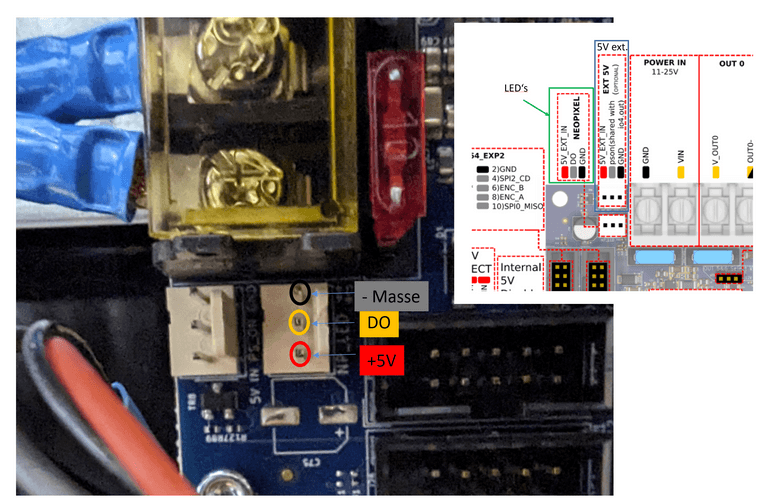
@Wobi I’ll wire up 3 RGBW lights tonight. This is how I wired up the RGB leads:
The strips have 3 connections; 5V, data and GND. I connected 5V and GND to the 5V and GND on IO_4. I connected data to the led pin on the LED connector by power in. I don’t have anything connected to 5V_EXT, and no jumpers on the 5V_Select or internal_5V_disable pins. So the LEDs are powered from the internal 5V regulator, which can supply 1A. 3 LEDs should pull maximum 0.24A, so unless you’re running something else on 5V (PanelDue and 12864 screen etc) as well (I ran a PanelDue on mine as well, no problem), this should be fine. You can also just turn on LEDs at low brightness, to reduce current usage.
Make sure the data line connects to Di (data in) on the first LED, not Do (data out). If you can post a picture, that would help.
Ian
Bed-slinger - Mini5+ WiFi/1LC | RRP Fisher v1 - D2 WiFi | Polargraph - D2 WiFi | TronXY X5S - 6HC/Roto | CNC router - 6HC | Tractus3D T1250 - D2 Eth
-
@droftarts said in Duet3 Mini5+ Ethernet Nozzle Distance to PEI sheet is too large:
12864
I have a 12864 display
-
@Wobi
Good morning Ian,
I've now measured again and I couldn't measure any voltage, the voltmeter shows 0 volts at the pins.
To be on the safe side, I also measured with the display disconnected, still 0 volts on + and -.
An external power supply was also unsuccessful, regardless of whether I supplied the board with 5 volts using the pin next to it or applied the 5 volts directly to the LEDs.
It seems like the DO pin is not outputting a signal.
Did I even use the correct pins for the Stealthburner LEDs or do I have to connect them somewhere completely different?Printing now works fine and fairly quickly. That's actually the main thing.
The cause of the crash was probably a larger blob on which the nozzle got stuck, it only has an M5 thread and is hollow inside, so not very stable.Another request, by repeatedly unplugging and plugging in the fan plug on the 1LC board, the cables broke off and now I also ran out of small pins to re-crimp.
Could you please tell me the exact name of the small pins so that I can get some?Thank you, Wolfgang
-
@Wobi I've now got RGB and RGBW LEDs working on Mini 5+, 6HC and Duet 2 WiFi, on both the dedicated 5V signalling 'led' pin, as well as 3.3V signalling pins like io_#.out. It should really not be difficult!
First, please send
M115in the terminal so I can check you are using the correct firmware; I know you said you updated, but please send this to check.On the Mini 5+, the NEOPIXEL header is only powered by External 5V; you can't power your LEDs from that header. However, the DO pin is active, and provides a 5V signal (not constant, only when you send an M150 command). So you need to connect the +5V and GND of the LEDs to somewhere else. If you only have 3 LEDs, you should be okay to use 5V from the Duet itself. I don't think the 12864 display draws that much current, so you should be okay to leave that connected.
So connect the LED +5V and GND to an IO header, or anywhere else that has a 5V pin and GND. Then connect the data wire to DO pin on the NEOPIXEL header. If you have a LED string configured for the 12864, make sure you're using different M950 E# numbers for each.
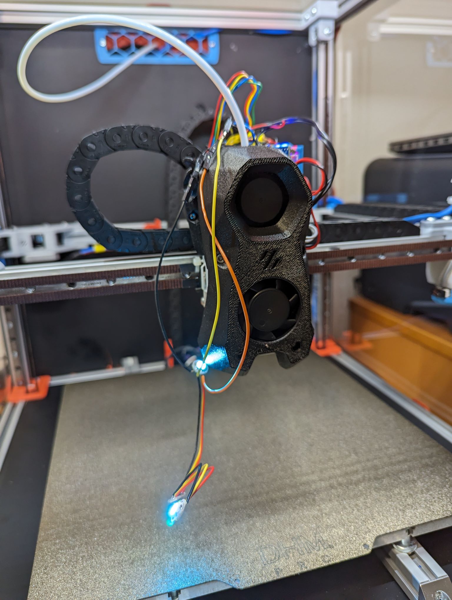
Let me know if that helps. If not, I'll take a picture of my setup. Also, please post a picture of your LEDs.
Ian
Bed-slinger - Mini5+ WiFi/1LC | RRP Fisher v1 - D2 WiFi | Polargraph - D2 WiFi | TronXY X5S - 6HC/Roto | CNC router - 6HC | Tractus3D T1250 - D2 Eth
-
@droftarts
Good morning Ian, the ones that were already installed still don't work, they are probably defective. I have now temporarily connected a new 2 euro set and after entering your GCodes the first one lights up red, the second green and the third doesn't light up at all. Power supply via the 5v PWM+, see photo. However, I only measure 3.6 volts on the third LED and after the ground PIN of the LEDs is broken, both of them continue to light up and I measure 5 volts on all LEDs again. So I will use an external power supply.
Which LEDs should I order or can I use the 2 euros?
And please, where can I order connectors for the 1LC board?
Thanks Ian
wolfgang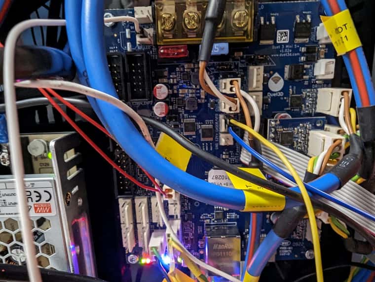
-
@Wobi Are the 5V power and GND the Blue and Yellow wires? If so, you've plugged 5V (blue) into 5V_EXT (which should be okay), but the yellow GND wire into 'out6_buff', not GND!
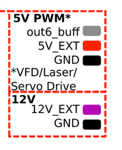
Move the yellow wire to a proper GND pin.
Ian
-
@Wobi said in Duet3 Mini5+ Ethernet Nozzle Distance to PEI sheet is too large:
And please, where can I order connectors for the 1LC board?
What connectors you need depend on which version of the toolboard you have.
See https://docs.duet3d.com/en/User_manual/Troubleshooting/Parts#connectors-used-on-duet-3-toolboard-1lc
and https://docs.duet3d.com/Duet3D_hardware/Duet_3_family/Duet_3_Toolboard_1LC#description-of-connections
Most likely it is a 3- or 4- pin JST PH. You can find pre-wired ones on eBay that you can solder your wires to, or the crimps and headers ready for crimping.Ian
Bed-slinger - Mini5+ WiFi/1LC | RRP Fisher v1 - D2 WiFi | Polargraph - D2 WiFi | TronXY X5S - 6HC/Roto | CNC router - 6HC | Tractus3D T1250 - D2 Eth
-
@droftarts
yes, it's true that it still worked.
Thanks for the links, that helps me.
greeting
wolfgang -
@Wobi
Hello Ian, thanks to your instructions and tips, I have now connected correctly and all three of the connected LEDs work perfectly. The built-in ones are probably broken.
I have to wait until I have the JST PH connectors to install it.This solved my problem, thank you very much.
Greetings Wolfgang
-
@Wobi Great! Glad you got it fixed in the end. Are the LEDs wired to the toolboard, or do the wires run back to the Mini 5+?
Ian
Bed-slinger - Mini5+ WiFi/1LC | RRP Fisher v1 - D2 WiFi | Polargraph - D2 WiFi | TronXY X5S - 6HC/Roto | CNC router - 6HC | Tractus3D T1250 - D2 Eth
-
@droftarts
The LEDs are connected to the Mini5 as described above -
@Wobi Okay. I'll try them on a 1LC when I get a chance, but I think the LEDs will need a level shifter, or 'hack' (I'm waiting for some diodes to be delivered to try this hack) to accept the 3.3V signal they will get from a 1LC io.out pin.
I haven't tested it, but I think the out6_buff pin (pin name
out6) should also be able to drive the LEDs as the data line, instead of DO on the NEOPIXEL header, as it is a 5V PWM pin. If you have wired 5V and GND to that header, it may be convenient for you to connect the LED data line there, too.Ian
Bed-slinger - Mini5+ WiFi/1LC | RRP Fisher v1 - D2 WiFi | Polargraph - D2 WiFi | TronXY X5S - 6HC/Roto | CNC router - 6HC | Tractus3D T1250 - D2 Eth
-
@droftarts
Good morning Ian, yes that would be an advantage as only one plug is needed.
But at the moment the LEDs are working perfectly, so there is no need to change them.
Now I need a hood to hide the tangled cables.
greeting
W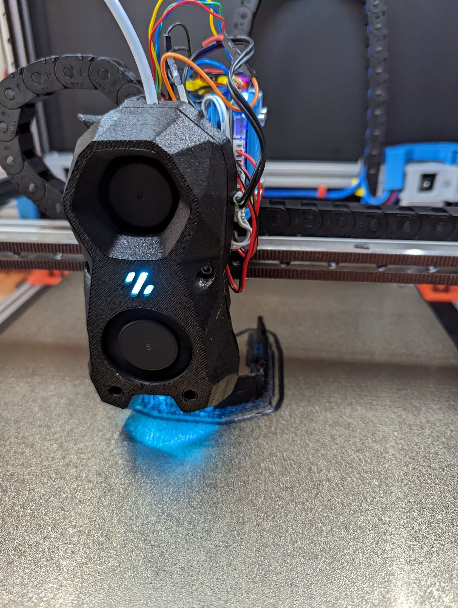 olfgang
 -
@Wobi
This thread can be marked as solved, thanks -
 undefined droftarts marked this topic as a question
-
undefined droftarts has marked this topic as solved
-
@Wobi Hello, may I ask you what mount you are using for the 1LC tool board? If you have a link that would be great. Thanks