Duet 2 Wifi Accelerometer Connectivity Issues
-
Hi all.
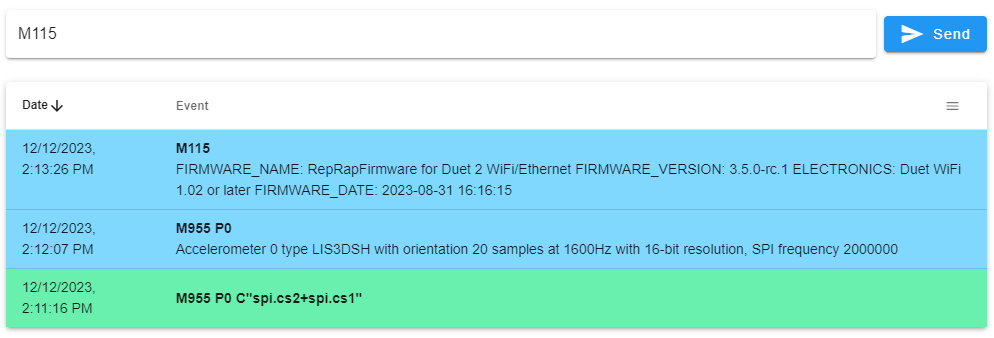
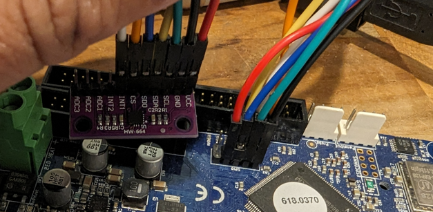
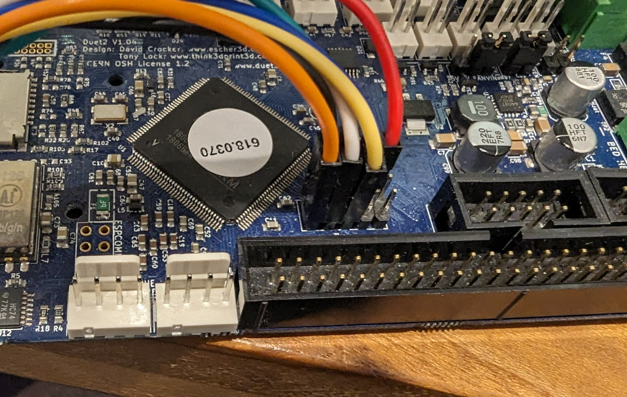
I am in the process of getting an accelerometer connected to one of my Duet 2 Wifi boards to allow input shaping, however I have hit an infuriating issue where the duet board on the machine I actually want this capability (a Tevo Little Minster delta) REFUSES to detect the device. Console screenshots and wiring shown below.
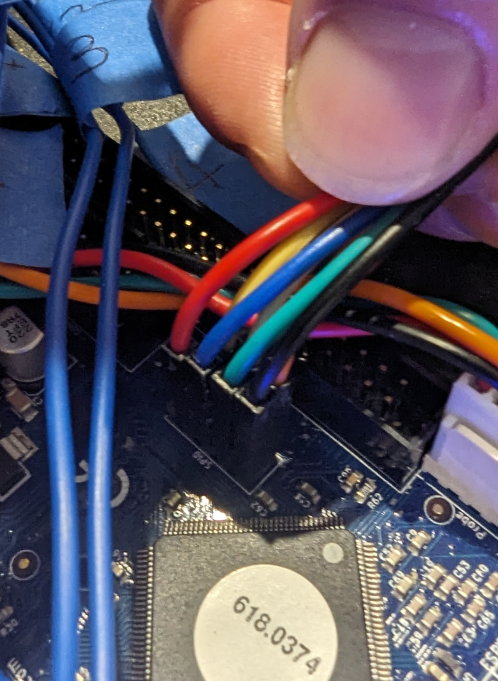
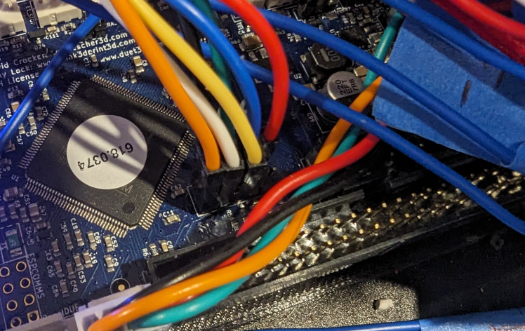
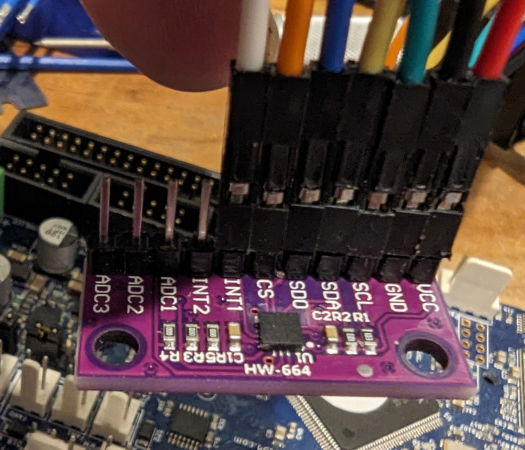
Wiring connectivity overview:
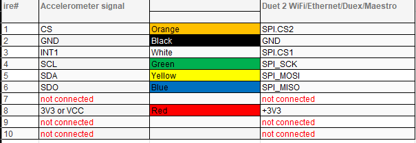
I checked and double-checked my wiring, updated firmware, swapped accelerometers (i bought a few), used shorter cables, wrapped them in foil to shield from interference (clutching at straws) but all to no avail.
As i had a spare Duet 2 WiFi board available, I did a bench-test with the same wiring loom, connected to the same Temp daughterboard IO pins, and the same accelerometer, same firmware versions, and it worked immediately. See screenshot
So as a test I pulled the SD card from the working board, put it in the board giving me problems, and it still errored. So this for me takes system config out of the equation.
So from troubleshooting i have confirmed:
- System config is not impacting connectivity.
- The wiring loom is tested ok
- The electrical connectivity between the Temp Daughterboard pins and the accelerometer is correct.
- The accelerometer tested ok.
So what from a hardware perspective on that particular Duet board could be impacting this connection? Is there anything that shares the IO that runs to the Temp DB connection? It is overall a pretty vanilla setup so i am a bit lost for ideas.
Thanks in advance for any assistance.
-
@bkdfkup As far as I can tell from the pictures, your wiring is correct on the first board, and the commands look correct too. I'd check the continuity through the wiring, and that the accelerometer board is receiving
5V3.3V. Apart from that, swapping the Duet boards, and seeing if anything you are connecting is causing the problem, or the back of the Duet is touching on anything conductive. Lastly, check the pins on the Duet are soldered correctly (one may have been missed), and there are no solder bridges between pins, on the back of the board.Ian
-
Thanks for the response @droftarts.
I have checked the voltage being received by the accelerometer and it was around the 3.3v mark. From what I have read that is the expected (or needed) voltage for signals to be at the 3.3v logic level. I did not test the supplied voltage on the working duet, so I will check that. Any confirmation on the 5v vs 3.3v would be welcome.
That aside, swapping boards and/or checking for shorts / unsoldered pins is the next step it seems. I will test accordingly and let you know what I find.
-
@bkdfkup Sorry, you are correct, 3.3V! I'm sure you have seen it, but here's our wiring instructions: https://docs.duet3d.com/User_manual/Connecting_hardware/Sensors_Accelerometer#wiring
Ian
-
Do you have a second accelerometer board to try?
-
@Phaedrux I do, and have tried with multiple.
-
In that case I suspect wiring quality. Some have had good results from using a USB3 cable as it is shielded internally.
-
So to update this post with my findings, a swap of the duet board into the Tevo with the same wiring, same accelerometer, and same SD card (and config) worked perfectly. The duet board I removed does not show any signs of having faulty solder joints (or bridged) so for now I am at a loss as to what's wrong with it or how to fix it.
-
When and where did you purchase the Duet that isn't working with the accelerometer?
-
I inherited it, and the others, off my neighbor. So i am not out of pocket financially, but also have little recourse to have it replaced (if it is even in warranty).
For some additional info i have done a full factory reset (wiped and re-flashed its firmware) to take firmware corruption out of the equation, however bench-testing showed this had zero impact.
-
@bkdfkup
you may want to try using > M955 P0 C"spi.cs4+spi.cs3"
I've had two boards that for some reason didn't work when connecting my accelerometers to it, but did via the daughterboard pinout command.
Probably wont work, but its quick and free so its worth a try.