Thanks. @jay_s_uk and @dc42 I have just applied the latest FW and am printing another test print. Will let you know how it goes.
Revisions are now:
Duet 2 WiFi 3.5.4
Duet WiFi Server 2.2.0
Duet Web Control 3.5.4
Thanks. @jay_s_uk and @dc42 I have just applied the latest FW and am printing another test print. Will let you know how it goes.
Revisions are now:
Duet 2 WiFi 3.5.4
Duet WiFi Server 2.2.0
Duet Web Control 3.5.4
First print after updating firmware went well using the same gcode as the last skewed print. No more skews, just some over-extrusion on the seam that needs some tweaking.
Hopefully the RC firmware was the issue. I'm running a second test now, and can hopefully call this one resolved.
First print after updating firmware went well using the same gcode as the last skewed print. No more skews, just some over-extrusion on the seam that needs some tweaking.
Hopefully the RC firmware was the issue. I'm running a second test now, and can hopefully call this one resolved.
Thanks. @jay_s_uk and @dc42 I have just applied the latest FW and am printing another test print. Will let you know how it goes.
Revisions are now:
Duet 2 WiFi 3.5.4
Duet WiFi Server 2.2.0
Duet Web Control 3.5.4
@dc42 good point sorry. Versions are:
Duet 2 WiFI 3.5.0-rc.1
Duet WiFi Server 2.1beta4
Duet Web Control 3.5.0-rc.1
To add to the above, i have increased the wall thickness of the test tube from 1.5mm to 2.4mm resulting in an extremely skewed print. The primary difference i can see is infill. With only walls making up thickness the model it prints correctly, with infill it skews.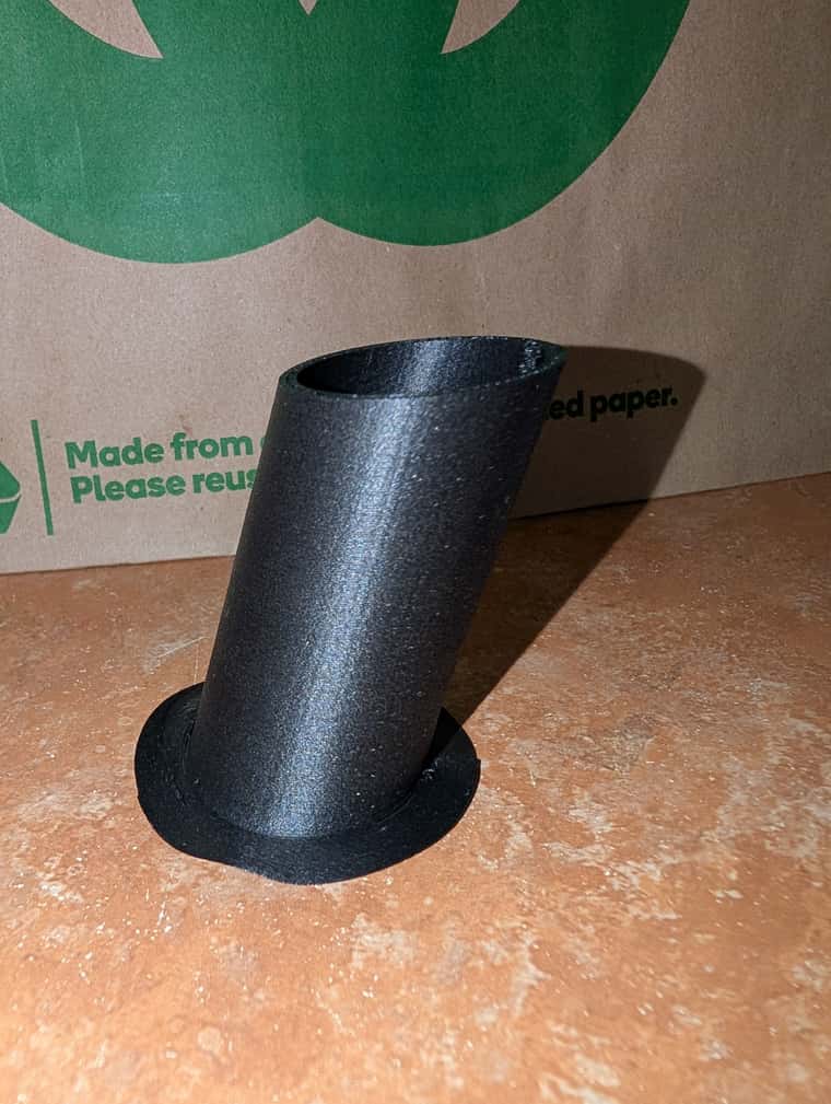
Hi forum members
Hoping for some assistance with an odd problem that has me chasing my tail. I have a Tevo Little Monster delta printer that is controlled by a Duet3D 2 Wi-Fi board.
The problem I'm facing is that some prints are drastically skewed, and some prints are near enough to perfect. I can re-slice and re-print the models that skew and get the same skewed outcome, yet the test models that print perfectly ALWAYS print perfectly, even if re-sliced. All models are being sliced using the same slicer (Cura version 5.7.1) and same settings
I've been through the dimensional measurements and the 6-point auto calibration multiple times and everything I can see checks out.
For the fact it can (when it feels like it) output a dimensionally accurate print, I feel the dimension config is correct, and this also seems to indicate the hardware is doing what it should (or at least what it's told) with no broken/loose belts or missed steps. The motors also do not appear to be overheating as has been a suggestion on other forum posts, and are only luke warn to the touch.
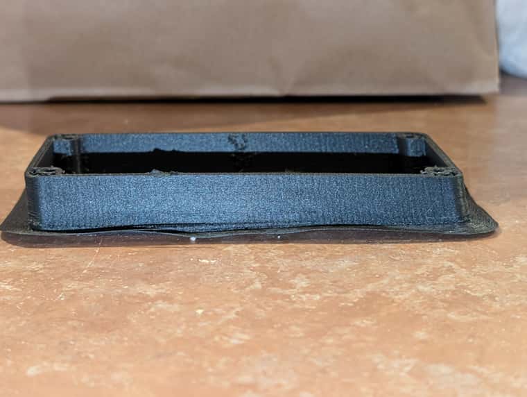
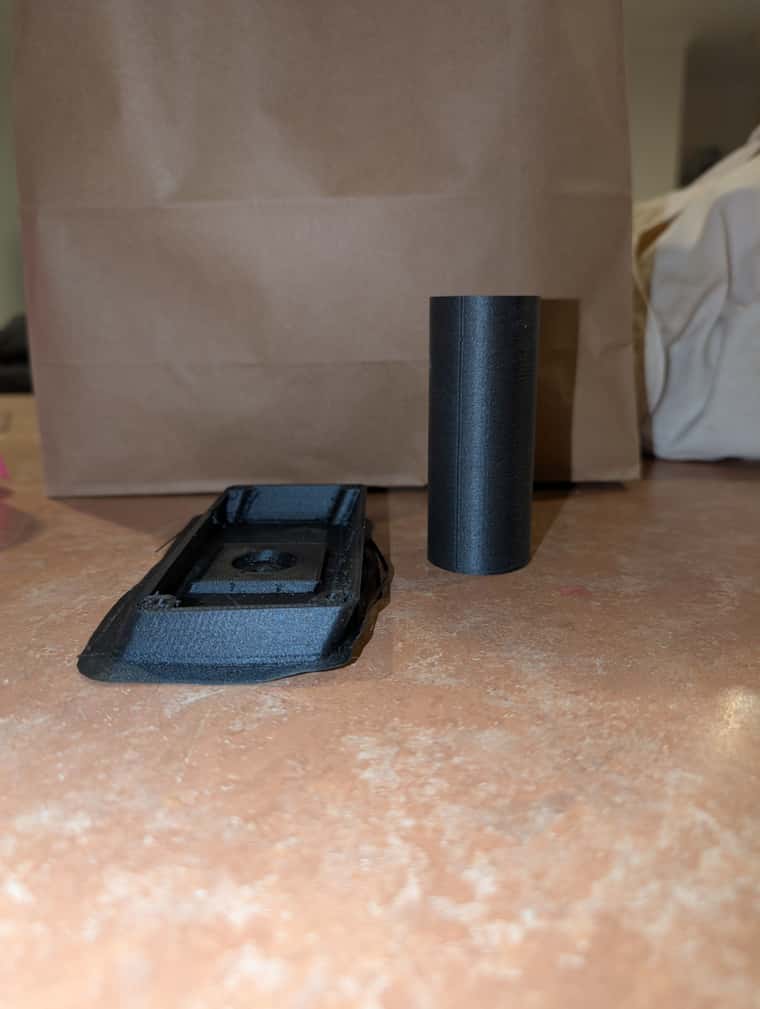
Attached are a few photos to illustrate the issue. One model that skews (a functional part that is a rectangular case that is 142mm wide, 62mm deep, and 34mm high, with 2.4mm walls), and the other (a 100mm x 50mm tube with 1.5mm walls) that prints as intended. I have also tried a 100mm x 50mm square tube to see if repeated acceleration / deceleration was the cause, but it also printed well.
So I'm at a loss as to where to look next, and would be grateful for any guidance. In the interim I'm trying to narrow down ways to replicate the issue with test prints by adjusting height, width, wall thickness etc.
Thanks in advance.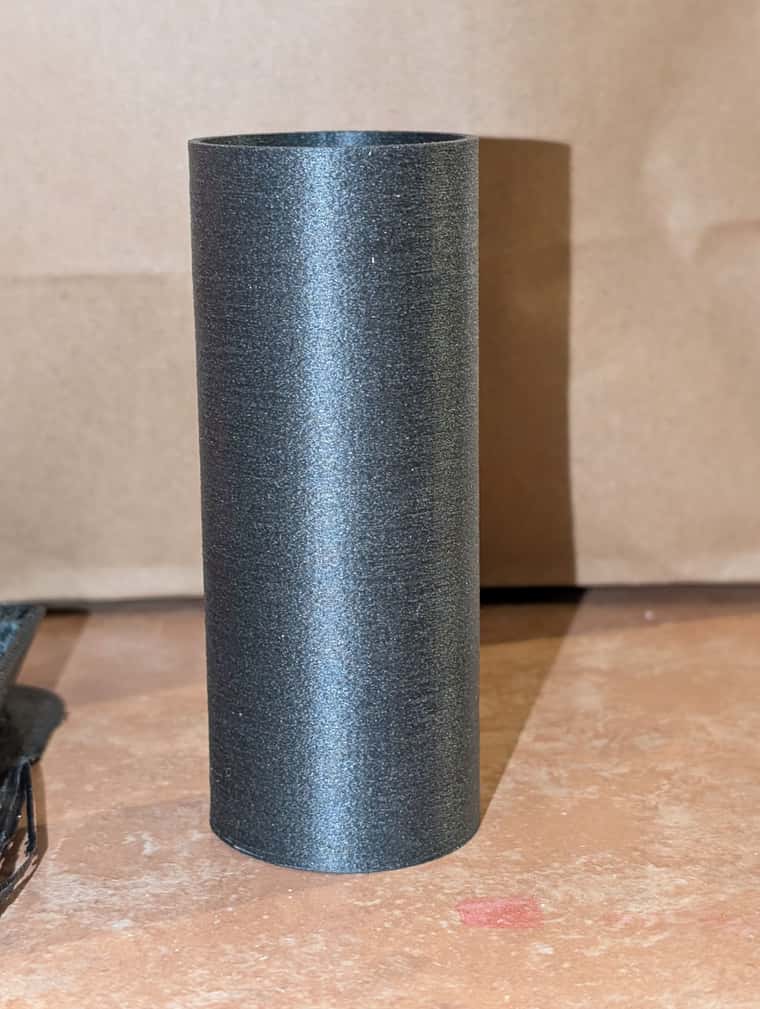
@dc42 said in Duet Smart Effector LEDs:
blown due to running the effector on 24V with jumper JP3 in
Thanks for the response, it was absolutely on-point. I will do some testing to try narrow it down.
I inherited it, and the others, off my neighbor. So i am not out of pocket financially, but also have little recourse to have it replaced (if it is even in warranty).
For some additional info i have done a full factory reset (wiped and re-flashed its firmware) to take firmware corruption out of the equation, however bench-testing showed this had zero impact.
I have a smart effector installed and working well on my delta printer with a duet 2 wifi. I have one issue though, as the LEDs intended to illuminate the print / build plate are not working at all, and have not worked since new. All fans are working perfectly (part and hotend fans) and as the LEDs are meant to light up whenever the hotend fan is working, I am not sure what's wrong without fully disassembling the smart effector assembly to check the traces and individual components.
I have tested on multiple duet boards too, not that that should change anything if the hotend fan is working as it should.
Any advice would be appreciated. Has anyone had similar issues?
So to update this post with my findings, a swap of the duet board into the Tevo with the same wiring, same accelerometer, and same SD card (and config) worked perfectly. The duet board I removed does not show any signs of having faulty solder joints (or bridged) so for now I am at a loss as to what's wrong with it or how to fix it.
@Phaedrux I do, and have tried with multiple.
Thanks for the response @droftarts.
I have checked the voltage being received by the accelerometer and it was around the 3.3v mark. From what I have read that is the expected (or needed) voltage for signals to be at the 3.3v logic level. I did not test the supplied voltage on the working duet, so I will check that. Any confirmation on the 5v vs 3.3v would be welcome.
That aside, swapping boards and/or checking for shorts / unsoldered pins is the next step it seems. I will test accordingly and let you know what I find.