Gap in printing concentric circles-(CW side)
-
Hi,
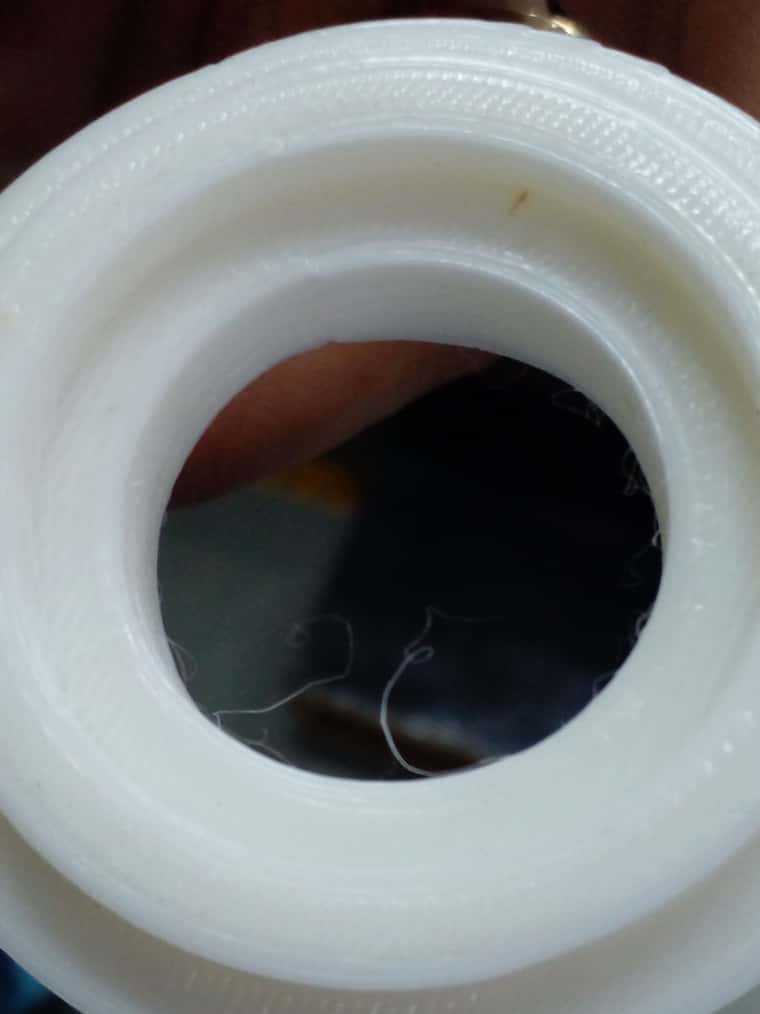
I am facing a problem in printing circular objects. Gaps in concentric circles & this continues across the height of the print. What can be the reasons for this?
b) This same gap appears exactly opposite side at 180degree.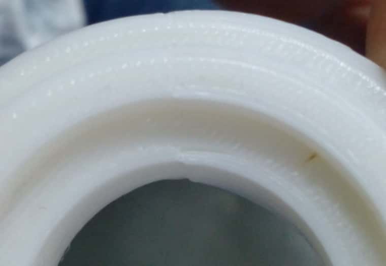
System description:
a) Belt driven. guide rod system.
b) config is fine, XY speed, steps/mm are all same. Square appear square.
c) dimension 280280290NOTE:
a) This gaps happens when direction of printing changes from CCW to clowckwise.Why this gap occurs during direction change?
-
@JayT Can you try to figure out if it's the XY movement or the extrusion?
Maybe tape a feltpen to the (cold) hotend and draw a circle on paper?If the gap was caused by backlash or tilting head, you'd notice it during both direction changes (CW-> CCW and CCW-> CW)
Maybe you'll see an overlapping circle in one direction and a gap in the other?If it doesn't come from the XY gantry, you might want to disable pressure advance and re-check your retraction settings.
A loose grub screw on a D-shaft stepper can cause gaps. (check XY and E-steppers)
If it's a CoreXY gantry, check the belt tension. Both belts must be equally tight or it can cause toolhead tilt. -
@o_lampe :
What you said in 3rd sentence is right. the circle overlap in one direction & gap in other. & at exactly 180degrees you will same gap. !
It's not coming from extruder or pressure advance either, as we see that the head position itself is different when it moves in CCW. & without these values set or changes in them, the gap doesn't change its form.
Mine is cartesian.
-
@JayT I've also seem your question about backlash-compensation, but on a different printer? In both cases I'd invest time to find and eliminate the cause.
Backlash compensation is just a temporary band-aid. If you don't find the cause, the required compensation can change for unknown reasons.Maybe your guide rods or the linear bearings are worn out? Rotate them a few degrees, so they run on a fresh surface, might help.
-
@o_lampe :
All guide rods & linear bearings are new, not more than a month old.
& yes, that backlash question is for different printer. However, I have same problem of concentric circle gap in that printer too.
 .
.Another observation is, if I loosen one of the X belts of the 2, the problem does increase i.e. gap increases . But when i tighten the same belt, the problem does not zero down.
I tried tightening all the belts.
How do I verify they are equally tight ? -
@JayT said in Gap in printing concentric circles-(CW side):
How do I verify they are equally tight ?
By ear. Plug them as if they were guitar strings. The belts are more important on a CoreXY.
On a cartesian printer you should see the hotend tilt only on one axis, unless the hotend-holder itself has play?
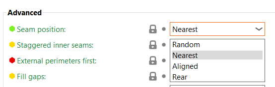
Did you try to slice the part with a different seam-position? -
@o_lampe :
Hotend seemed to have a play, however, after tightening it, I still see the same amount of gap & problem.
What do you mean by different seam position ? example? I am printing a circular object.
-
@JayT In most slicer you can choose where the seam is located. The seam is where an external perimeter starts and end, it usually creates an irregularity at that point
Prusaslicer
-
@modl :
Seam is not the issue. If we change this, it does not reduce gap.
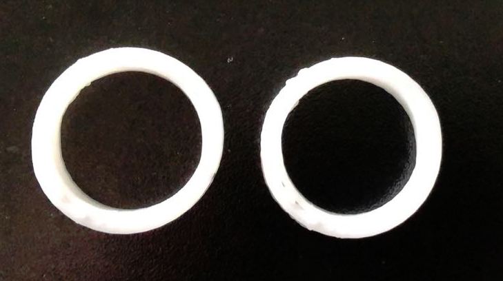
Backlash does though. But even then I see the flatness at the top & bottom surfaces of the circle.I also observed very less similar flatness in left & right most sides of the circle. Is this due to some slippage?
-
@JayT Indeed, it may not reduce the gap, but at least, if you set it otherwise, it will change gap position?
-
@soare0 : I tried. The major deformations that I see are along Y direction & X direction, just when either X or Y axis is changing its direction of movement while drawing a circle. Gaps reduce with backlash set. However, I see circle little flat on those points, instead of proper arc . - thats the major problem.
-
@JayT
This behavior can be based on binding of the linear bearings or skewed axles.
I had the identical issue. After changing the bearings to higher quality ones, the problem was solved.
Remove the belts and move the axles by hand. they should not snap when the direction is changed.
This may be caused by linear axles not being aligned exactly parallel.
Can you show pictures of the mechanics?Edit:
You can also see that the wall thickness varies a lot.
-
Re-alignment & belt tightening & ensuring perpendicularity of XY is something I re-checked again. The problem greatly resolved afterwards by using backlash compensation M425 with S factor lower than 10.
@o_lampe
@DIY-O-Sphere
Couple of questions:- Is there any way I can verify the linear bearings quality as per your suggestion?
- How do we set exactly same tension in X & Y axis belt. Is there any procedure or method ? Because the moment this tension changes, it will affect the learned backlash value
-
@JayT
I first had plain bearings that were changed to linear ball bearings. But install branded bearings here. I once had cheap bearings for Z that worked very badly. You notice it when you move the separated bearing by hand. They have an uneven, choppy running. Especially when changing direction.
Which cannot be checked when installed:
Put the bearing on the rod and tilt it until it starts running on its own.
Then tilt the rod to the other direction.
On the subject of tilting or distortion of the axle:
Push the axis to one end and check whether the axis comes to rest on both sides at the same time.
Push alternately on one side or the other.