Duet 3 Mini 5 to Duet 3 Toolboard
-
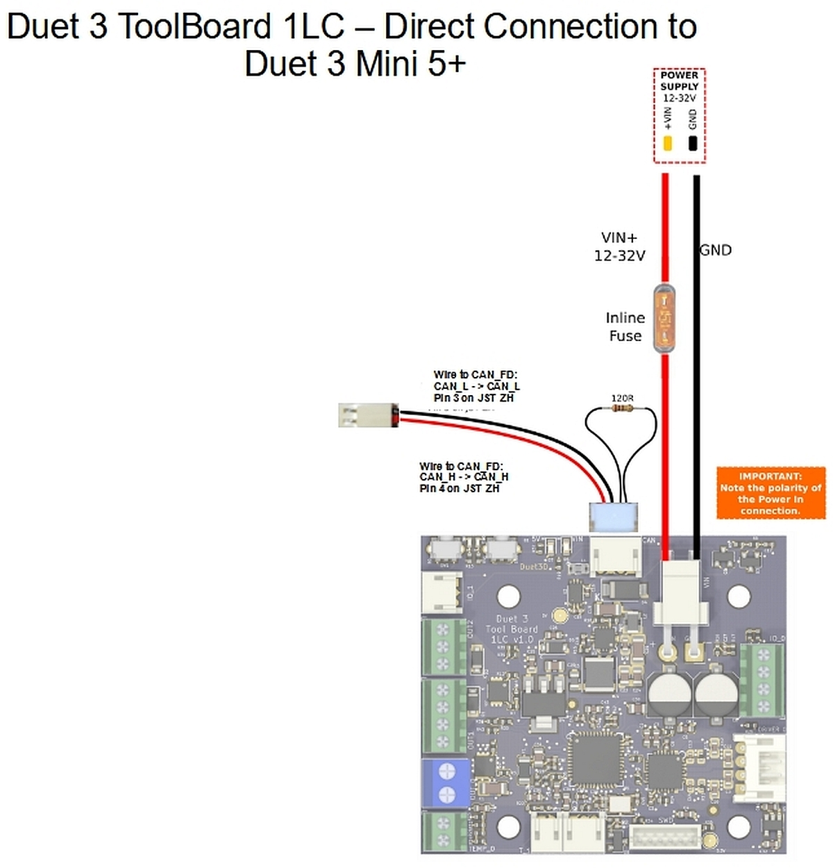
I am modifying another Lulzbot Workhorse. It'll be running a Hemera XS w/ a Duet 3 Toolboard from a Duet 3 Mini 5. I have a couple questions that I'd like clarification on from the documentation in regards to wiring IOT proceed safely. https://docs.duet3d.com/Duet3D_hardware/Duet_3_family/Duet_3_Toolboard_1LC tells me to use an inline fuse. I purchased https://www.amazon.com/gp/product/B081YGN8SP/ref=ppx_yo_dt_b_asin_title_o00_s00?ie=UTF8&psc=1 . What size fuse do I need to purchase for a E3D Hemera XS? It tells me to "pick the lowest rated fuse appropriate for your heater and motor current draw." But I don't know it or where to find it.
Also, I was looking at how the toolboard is wired. I understand the +/- from the 24v power supply to the toolboard providing it power. However, I'd like some clarification on the wiring to the CAN FD. If I'm reading it correctly, red/black to the motherboard and white/yellow connected together. Then I have to solder the 120r CAN Bus Termination (little spot on the back of the toolboard). Am I understanding that correctly. I don't want to solder something I shouldn't and ruin the toolboard. This is my first toolboard and I want to be certain. Thank you in advance for any guidance you can provide. I'm sorry if I haven't provided enough necessary information. Please don't hesitate to ask for more if necessary.
-
@SonnyD1 divide Watts by Voltage to derive the current from the Watt rating of the heater element in your hemera. Measure resistance of the heater cartridge to derive Watts using Ohms Law.
A 40W 24V cartridge draws about 1.8A
Computing the actual current of a motor is a bit difficult as the rated current only applies to rated voltage. For a.somewhat safe margin, assume twice the rated current of the Hemera drive motor. Dont forget the cooling setup with another 0.5 to 0.8A (but refer to your fan ratings to be sure, some funky setups use 12V 2A part cooling fans that will require external power).
-
@oliof 5A is what I got. The fan is listed as .04 and the motor is 1.4. What about the soldering job? Do you know about that? Thank you.
-
-
@oliof Right. I read that. The directions say I have to solder the 120r CAN Bus Termination (little spot on the back of the toolboard). Am I understanding that correctly. I don't want to solder something I shouldn't and ruin the toolboard. This is my first toolboard and I want to be certain.
-
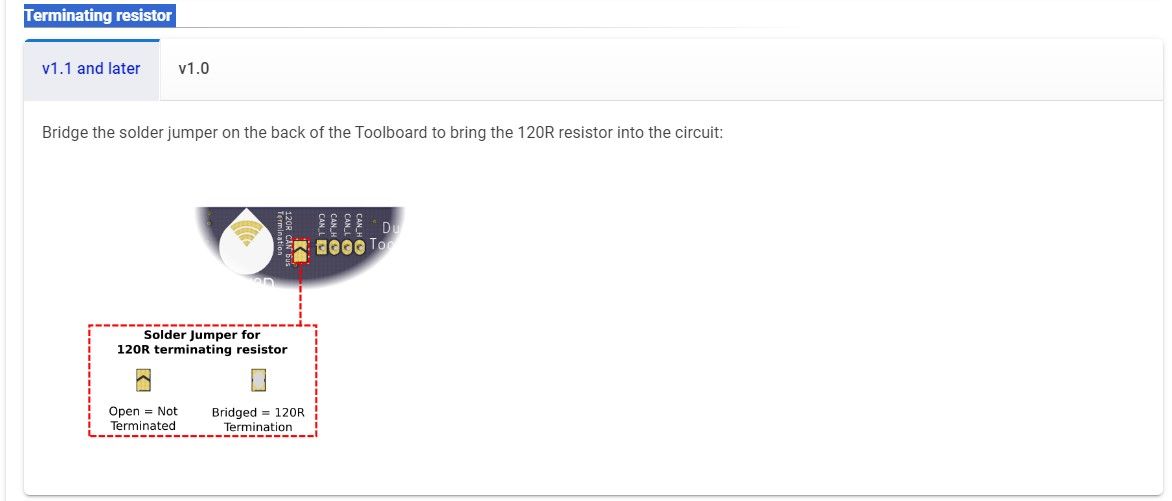
@SonnyD1 sorry I cannot find the reference to soldering for a Terminator and the image clearly shows how to add an external resistor without any changes to the board.
-
Its right under the image you posted. You have to select the correct board for it to display. It looks to me that latest board version has a resistor built in. It looks to me, and I'm obviously not an expert, that if I connect the white and the yellow wire, then solder this spot, it brings a resistor into the circuit. I'm really just looking for a second opinion to ensure I'm understanding it correctly.
-
@SonnyD1 you don't need to connect the white and yellow wires at all. Just connect the red and black ones to the Mini, and bridge the termination pads on the tool board.
Duet WiFi hardware designer and firmware engineer
Please do not ask me for Duet support via PM or email, use the forum
http://www.escher3d.com, https://miscsolutions.wordpress.com -
@dc42 Ok...Thank you very much. I'm sure I'll need your help again when I start to configure this thing.