CNC Parallel SCARA Plasma Cutter - GCODE Issues
-
@NortonAntivirus A gcode-generator doesn't care about your kinematics. It only tells where to go, but not how to get there.
That's part of the RRFirmware and it's identical in FFF or CNC mode.
Homing and start/end procedures may have to be edited and also the workspace limits are different for a SCARA.
There are minor differences in CNC mode and mostly Duet Web control related. The UI is different but not the kinematic. -
@o_lampe Thanks for your help! I have managed to get the machine working with Fusion 360. Does anyone happen to have a calibraiton procedure? I have tried measuing arm lengths, homing positions and end effector positions to calculate homing offsets etc, however I am struggling to get the machine to draw circular circles and to make shapes that are the correct size. If anyone has a good methodology for calibration please let me know ! Thanks
")
-
@NortonAntivirus apart from searching the forum, have you seen the wiki page? https://docs.duet3d.com/en/User_manual/Machine_configuration/Configuration_SCARA
There’s a calibration section at the end of the page. Any feedback to improve the documentation gratefully received!Ian
Bed-slinger - Mini5+ WiFi/1LC | RRP Fisher v1 - D2 WiFi | Polargraph - D2 WiFi | TronXY X5S - 6HC/Roto | CNC router - 6HC | Tractus3D T1250 - D2 Eth
-
@droftarts I am more than happy to write up my findings and help with the documentation. I think last night I discoevered that the M350 command doesnt have an effect, and instead off scaling values for microstepping etc need to be incorporated into M92. I am now looking into why the joints aren't moving the correct amount, It may be because of my closed loop stepper drivers so once i've done some learning I will feed back the information
-
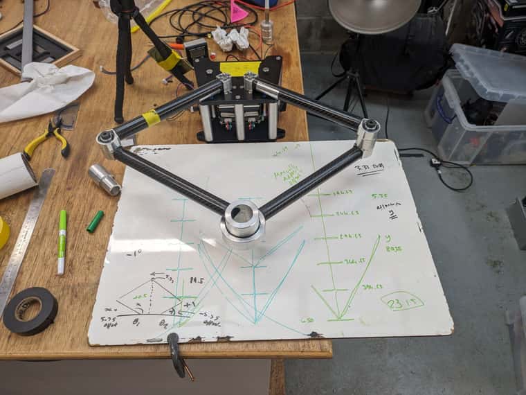
So a little update, I have spent a long time trying to calibrate things. I am currently using servo42c drivers, because my testing shows they increase torque from the little nema motors massively. I think my right gearbox and servo42c arrangement may be damaged, as it doesn't seem as repeatable as the left motor assembly. I think I may laser cut a grid to use as a positioning template so I can see difference between intended end effector position and achieved position. I have been using a whiteboard and a pen for this so far but it's not ideal. Both my motors are able to be manually driven from 90 degrees to horizontal and align nicely. I think maybe my arm lengths are wrong, as the aluminium piecesal are glued into the carbon tubes their lengths aren't very precise. I've tried to account for this but I don't think it's very good yet.
-
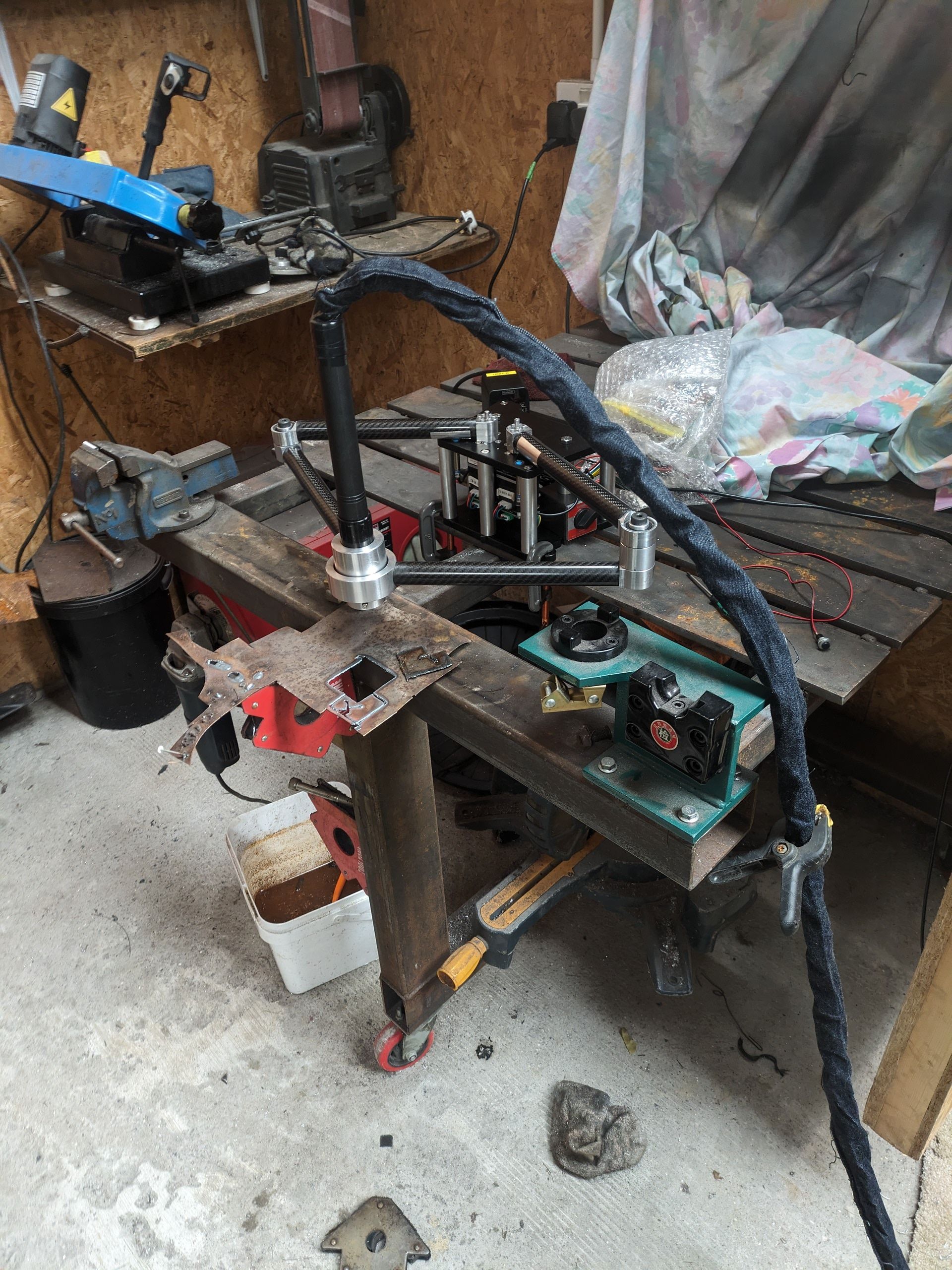
@NortonAntivirus YIKES!
Seeing a bandsander and a miter saw in the same room with a plasma torch is giving me the creeps. I hope it's only temporary?
The sparks of the torch can fly upto 10meter wide and are a serious fire hazard.
Woodchip walls are no good idea either.I've placed my torch on a water tank.
-
@o_lampe Just a temporary setup, ultimately I will make a proper table and area for it but only once I've got it working somewhat nicely
-
Hello everyone,
I have a slight update: I am unable to draw circles... it transpires that one of my gearbox and motor assemblies has a lot more backlash, resulting in around 7mm of inaccuracy at the end effector in working positions. I would like to add encoders to the output shafts of the gearboxes. Is this something that can be achieved in reprap firmware? I cannot seem to find anything about it. Ideally I would use 2 of these as I already have them from a past project. Once again, any help would be greatly appreciated. Many thanks!
https://uk.rs-online.com/web/p/mechanical-rotary-encoders/7899490 -
@NortonAntivirus said in CNC Parallel SCARA Plasma Cutter - GCODE Issues:
Hello everyone,
I have a slight update: I am unable to draw circles... it transpires that one of my gearbox and motor assemblies has a lot more backlash, resulting in around 7mm of inaccuracy at the end effector in working positions. I would like to add encoders to the output shafts of the gearboxes. Is this something that can be achieved in reprap firmware? I cannot seem to find anything about it. Ideally I would use 2 of these as I already have them from a past project. Once again, any help would be greatly appreciated. Many thanks!
https://uk.rs-online.com/web/p/mechanical-rotary-encoders/7899490May want to start a new thread with this question for better visibility.
-
@Phaedrux will do thank you!
-
 undefined NortonAntivirus has marked this topic as solved