DIY IDEX, Mini5+, Roto Toolboard and CAN-Bus Issues
-
Hi Guys,
I have designed and built an IDEX CoreXYU Printer using Duet components. The printer is equipped with a Duet3D Mini5+, one Tool Distribution Board, and two Roto Toolboards. Currently, I am facing issues with the wiring of the CAN-Bus. The Mini5+ and the toolboards have 2-pin connectors, while the Distribution Board has 4-pins. Initially, I attempted to connect them using 2-pin drilled wires, but unfortunately, the boards did not establish a connection.
Due to the wire lengths being approximately 1m, I tried creating a wiring setup with two junction boxes placed after the Mini5+ and between the Distribution Board and the toolboards. However, I have not been successful in establishing a connection.
I also tried a direct connection from one toolboard to the Mini5+, but they still do not communicate with each other.Could anyone provide me with information regarding the correct wiring based on my specifications, please?
Thank you.
-
@trulm said in DIY IDEX, Mini5+, Roto Toolboard and CAN-Bus Issues:
I also tried a direct connection from one toolboard to the Mini5+, but they still do not communicate with each other.
If you have two roto toolboards you will need to get this direct setup working first to allow you to change the CAN address of one of the boards, have you been able to do this? If not see here: https://docs.duet3d.com/en/Duet3D_hardware/Duet_3_family/Duet_3_Roto_Toolboard#can
When you tried the direction connection did you have the terminating resistor fitted to the roto board? You will need this to allow the direct connection to work.
-
@trulm I've been meaning to draw some diagrams for this page https://docs.duet3d.com/en/User_manual/Machine_configuration/CAN_connection but there really are a lot of different, and equally valid, ways to wire CAN.
For connecting the Roto toolboards to the Tool Distribution Board (TDB), you can wire them as stubs straight from that. See the wiring diagram here: https://docs.duet3d.com/Duet3D_hardware/Duet_3_family/Duet_3_Tool_Distribution_Board#wiring-diagram
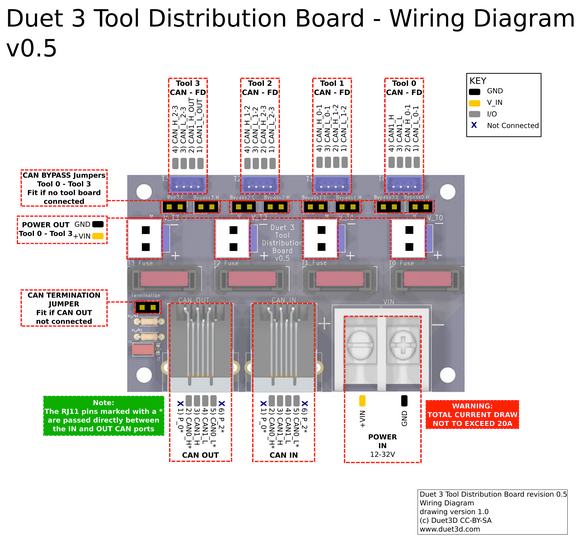
Plug the Mini 5+ into the TDB CAN IN RJ11 port. You'll need to make up a cable to connect the Mini 5+ 2-pin KK CAN connector to an RJ11 plug.
The CAN bus uses differential wiring, which means you need to connect each CAN_H pin to the CAN_H pin on the the next board, and each CAN_L pin to the CAN_L pin on the next board.
To wire the TDB with stubs, start with the Tool 0 output. Connect wires from CAN_H and CAN_L to CAN_H and CAN_L on the first Roto. This is now a 'stub' on the CAN bus; the CAN bus won't continue on from the toolboard. The wires to this toolboard should be under 1m long. Leave the CAN bypass jumpers for Tool 0 on the TDB in place; these will connect the CAN bus on to...
The Tool 1 output on the TDB. Again, connect wires from CAN_H and CAN_L to CAN_H and CAN_L on the second Roto. Again, this is a 'stub'. Each stub should be under 1m long, and the total length of stubs on the CAN bus shouldn't be more than 5m. Again, leave the CAN bypass jumpers for Tool 1 on the TDB in place, which will loop the CAN bus on to...
Termination. Don't fit the termination jumpers on the Roto toolboards. Fit the termination jumper on the TDB.
A @gloomyandy says, you'll need to set up each Roto board one at a time, to set the CAN address of each one. The advantage of the above wiring scheme is that you can just disconnect each toolboard from the TDB, you don't need to change any other wiring.
Ian
Bed-slinger - Mini5+ WiFi/1LC | RRP Fisher v1 - D2 WiFi | Polargraph - D2 WiFi | TronXY X5S - 6HC/Roto | CNC router - 6HC | Tractus3D T1250 - D2 Eth
-
@droftarts said in DIY IDEX, Mini5+, Roto Toolboard and CAN-Bus Issues:
leave the CAN bypass jumpers for Tool 1 on the TDB in place, which will loop the CAN bus on to...
I thought that unused ports kept the jumper ?
Love my Duet 3 Mini.
https://www.instagram.com/proschi3d
https://youtube.com/@proschi3d
https://www.proschi3d.de -
@Proschi78 said in DIY IDEX, Mini5+, Roto Toolboard and CAN-Bus Issues:
@droftarts said in DIY IDEX, Mini5+, Roto Toolboard and CAN-Bus Issues:
leave the CAN bypass jumpers for Tool 1 on the TDB in place, which will loop the CAN bus on to...
I thought that unused ports kept the jumper ?
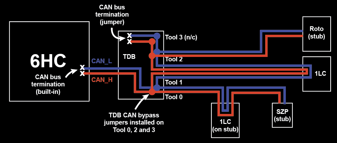
Yes, they do, I didn't say to remove them. Tool 0 and Tool 1 are stubs, so they keep their jumpers too, so all bypass jumpers stay in place. Then the TDB can provide the termination. See this diagram I did for the thread here: https://forum.duet3d.com/post/339187
Ian
-
Hi,
Thanks for your quick support.
The main issue was the misplaced termination jumpers and the unnamed toolboards. Now the boards are talking to each other.Thank you