automatic 3 axis bed levelling: kinematic versus maxwell mount
-
Hi Zusammen, I hope I dont mix up the terms here but nevertheless:
I wonder which geometries are supported by the firmware for autolevelling and mesh compensation since a classic kinematic mount would have the center of rotation/virtual pivoting point at the middle/rear axis, a v-groove at the front left (pointing towards middle rear axis) and an unconstraint plate at the front right axis e.g., whereas with a Maxwell mount, one would have three v-grooves pointing towards the center of the bed, which in turn would be the virtual pivoting point, correct?
In the configuration you can tell the code where you pivoting points are but in a Maxwell situation, everything tilts around the central point and not actually around the three axis pivot points opposite to the situation of a classic kinematic mount so I dont actually know for which situation the code for autolevelling is designed for??
-
@stellator Maxwell clamp as reffered to a way of 3 axis print bed levelling
-
@stellator
I think you're getting two things mixed up.
One is the mounting of the plate. And the other is the kinematics for levelling. First of all, these are not necessary related.
What you mean by virtual pivot point is the point around which the tolerance compensation occurs in a static system.
The kinematics could be attached to completely different points. Usually, however, the balls are used. These then become the points around which the plate can rotate as a system.
For the firmware, it doesn't matter where the virtual point is. The plane is defined by the three points that are attached to the plate and can be adjusted in height...... -
@stellator I think most people use these maxwell mounts to compensate thermal expansion of a heated bed. For those cases @DIY-O-Sphere is right: it doesn't matter.
But if you plan to angle the bed while printing, the center of rotation will not necessarily be the bed center, I guess? -
Thanks for your quick replies!!
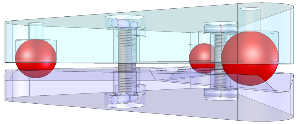
And I am glad to hear that the firmware can cope with any geometry as long as I can provide the correct coordinates!Also I decided to not go for the first version (image 1) but for the maxwell design (image 2) because then the printbed will tilt around the center of the triangle instead of the middle rear axis. I expect any future firmware that might support tilting the bed whilst printing to operate with the center of rotation be equal to the center of the coordinate system X=0 Y=0, at least that would result in the biggest possible print area in a tilting bed scenario. So yes, its intended be "tiltbed ready"
")
Now lets see how to actually home a core xy and soon it might come alive: Turn both motors in one direction until Y endstop is triggered and then rotate both in opposite directions until X is triggered? Hmm - that should do it...

-
@stellator said in automatic 3 axis bed levelling: kinematic versus maxwell mount:
Now lets see how to actually home a core xy
See https://docs.duet3d.com/en/User_manual/Machine_configuration/Configuration_coreXY#homing-files
Ian
-
@stellator Your first illustration is a Kelvin type kinematic mount. Both Kelvin and Maxwell mounts accomplish the task of allowing the bed plate to expand laterally without bending any mounting screws or causing the plate to flex or lift. The main differences between them are that the Maxwell mount reference point is at the intersection of the three grooves while the Kelvin mount reference point is at the hole or cone in which a ball sits. The other difference is that the Kelvin mount axes can be aligned with the X and Y axes in a machine making it especially easy to tram the bed because adjustment to the roll doesn't affect the pitch of the plate. With a Maxwell mount the axes are usually aligned 120 degrees apart so adjustments at any one point affect both the pitch and roll of the bed, making tramming a little trickier.
This is the bed support in my printer, designed as a Kelvin kinematic mount. The axis with the two spherical screws is aligned parallel to the printer's X axis. One of those balls (the reference) sits in a hole in the bed plate, the other (the pitch adjuster) in a groove that runs parallel to the X axis. The third point (roll adjust) is just a screw that touches the smooth bottom surface of the bed plate. The bed plate has ears for the three adjusters/support screws and is held down on the screws by springs. The reference screw doesn't normally get adjusted when tramming the plate. Tramming is done with a piece of paper between the bed plate and extruder nozzle. Simply adjust the Z position of the nozzle near the reference screw until it just catches the paper, then move the nozzle along the X axis until it is near the pitch adjuster and adjust until it just grabs the paper. Finally, move the nozzle near the roll adjuster and adjust until the nozzle just catches the paper and it's done. The last time I trammed my printer was almost 2 years ago.
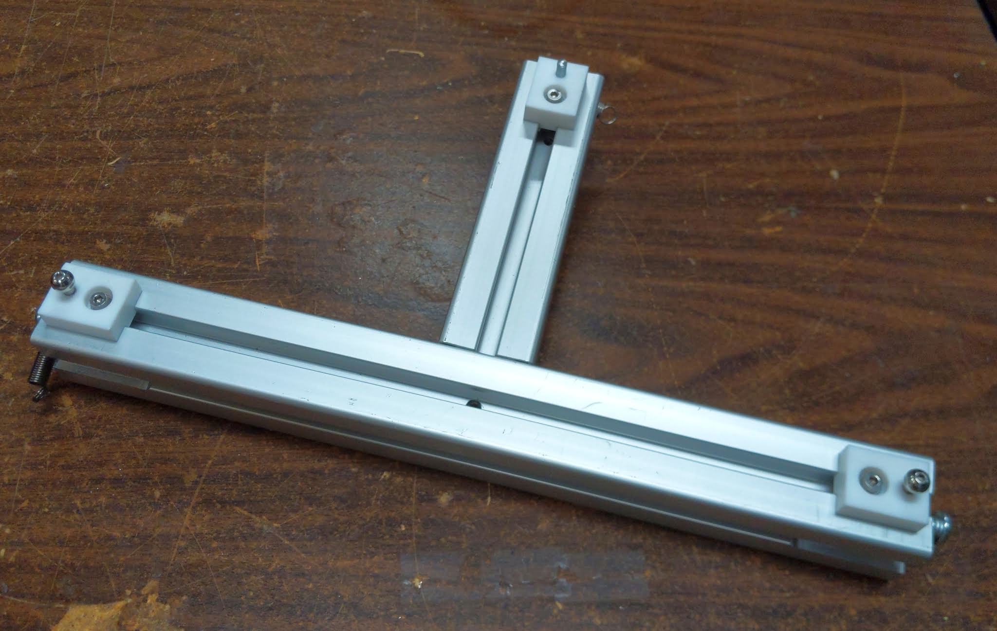
The reference screw sitting in its hole in the bed plate:

Here's the whole thing:

All three adjusters are mounted in PTFE blocks that grip the screws firmly but still allow them to be turned for tramming. They also don't mind the heat from the bed plate. If you make anything like this, don't use nylon instead of PTFE. you won't be able to turn the screws (I know, I tried). There's a reason they use nylon in nylock nuts! You don't need to tap the PTFE blocks. Just make slightly undersized pilot holes and thread in the screws. They will roll their own threads into the PTFE.