Using tool distribution board for multiple Motors 23CL
-
@dc42 Thanks for the info. That will help simplify the wiring.
-
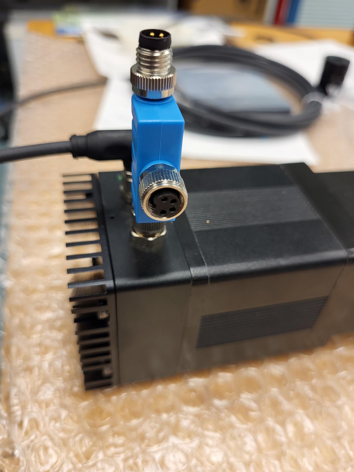
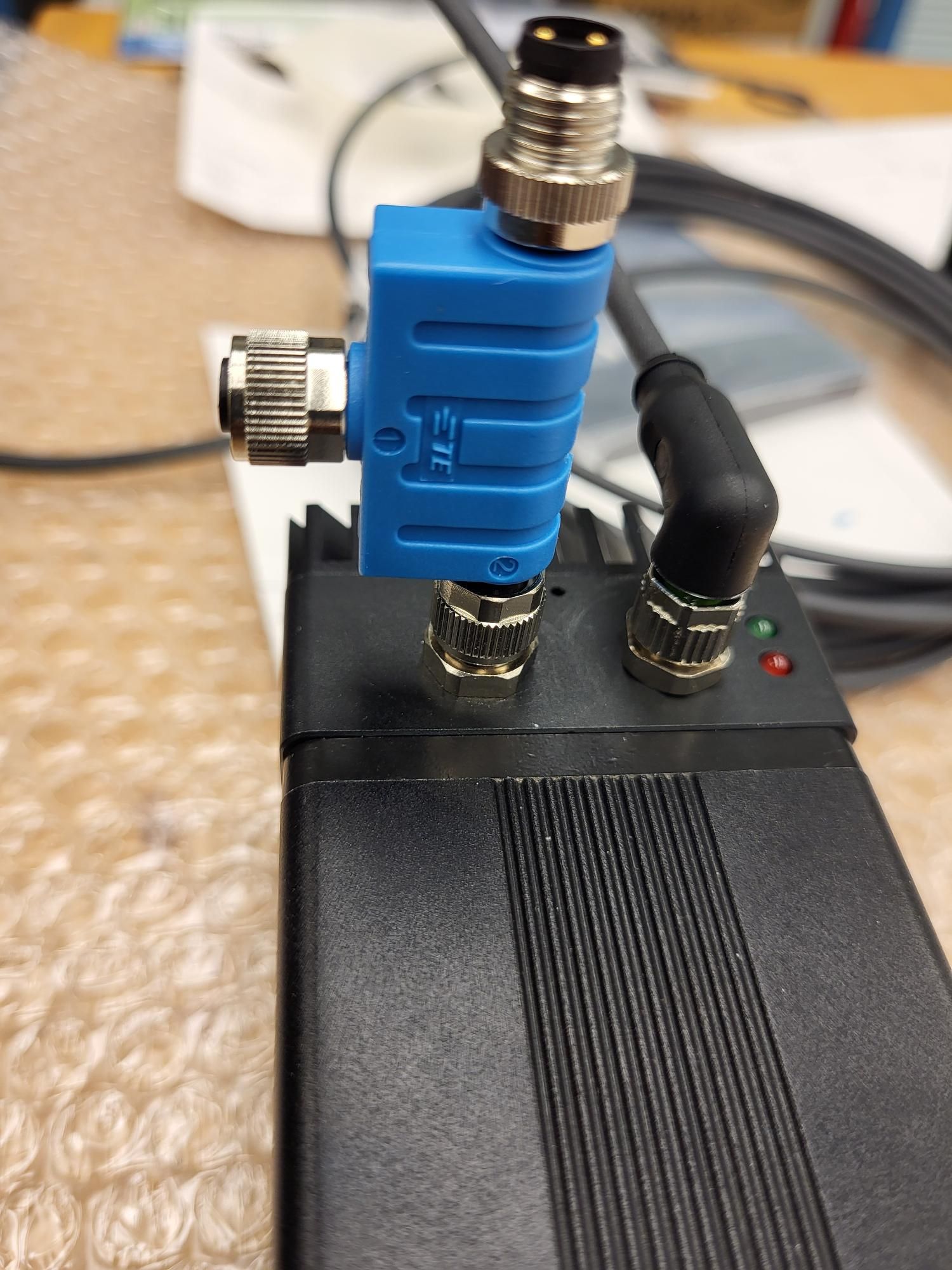
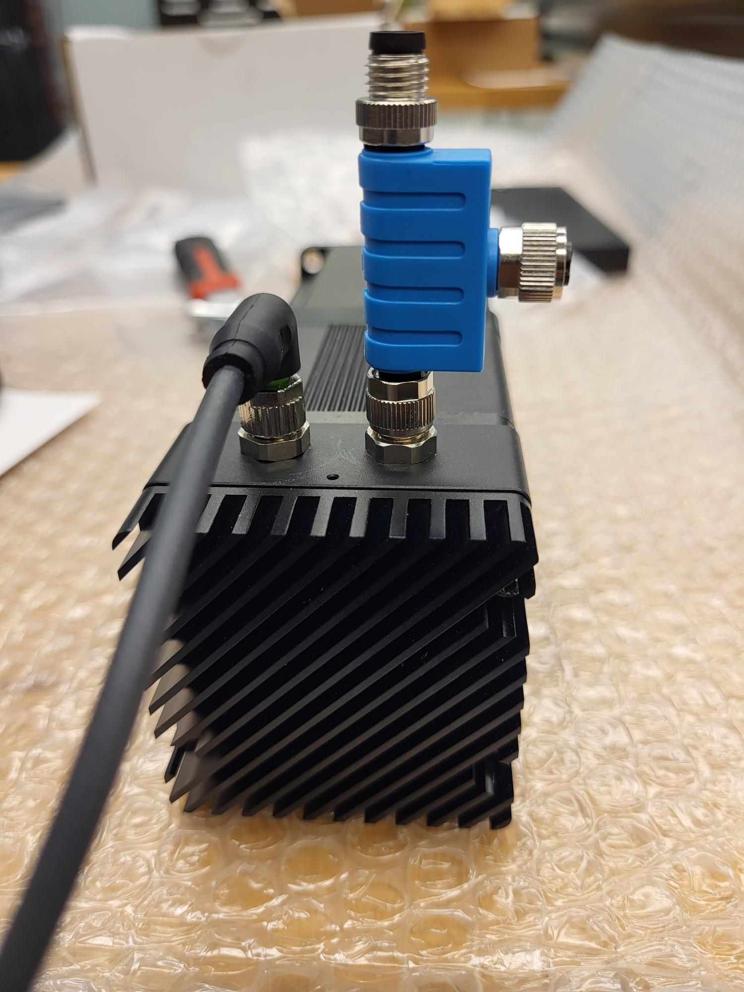
@droftarts Ian, I got hold of the T-splitter and I am not sure how to connect the CAN wires (See pictures below). Is this supposed to work in a daisy-chain fashion where one end of the T-splitter (motor-1) is connected to another end in a different T-splitter (motor-2) and so on?
And btw, looks like the T-splitter can only be connected in one direction and will collide with the M8 connector of the power port if connected otherwise.
-
@RockB We generally envisaged using the T splitters with a short cable between the T splitter and the motor, as we say here: https://docs.duet3d.com/Duet3D_hardware/Duet_3_family/Duet_3_Motor_23CL#can-wiring
The 23CL has two pairs of CAN_L and CAN_H connectors, so it should be relatively easy to loop on to the next motor, or back to the Tool Distribution board. Either way, CAN_L connects to CAN_L on the next board, CAN_H connects to CAN_H. See https://docs.duet3d.com/User_manual/Machine_configuration/CAN_connection#wiring-scheme
The Tool Distribution board effectively does the loop internally. If you only have one motor connected to a 'Tool' connector on it, you can wire it just with a 4-wire cable.
The Roto toolboards can be wired as stubs if they are less than 1m. See the above link for details on them. If a stub (two wires) is connected to a TDB, leave the jumpers on the TDB for that tool.
Looking through your connections, it looks like you don't need to use the T splitters, as you only have one drive on each TDB 'Tool' output.
If you need more info than that, or an outline wiring diagram, let me know.
Ian
Bed-slinger - Mini5+ WiFi/1LC | RRP Fisher v1 - D2 WiFi | Polargraph - D2 WiFi | TronXY X5S - 6HC/Roto | CNC router - 6HC | Tractus3D T1250 - D2 Eth
-
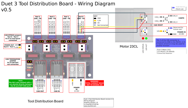
@droftarts Hi Ian, Thank you for the suggestions. To make sure I understood this correctly, I can directly wire the 4-pin M8 wire from the CAN port of motor 23CL to T0 of the tool distribution board (TDB) making sure CAN_L and CAN_H are the same on both ends. Is the following wiring correct?
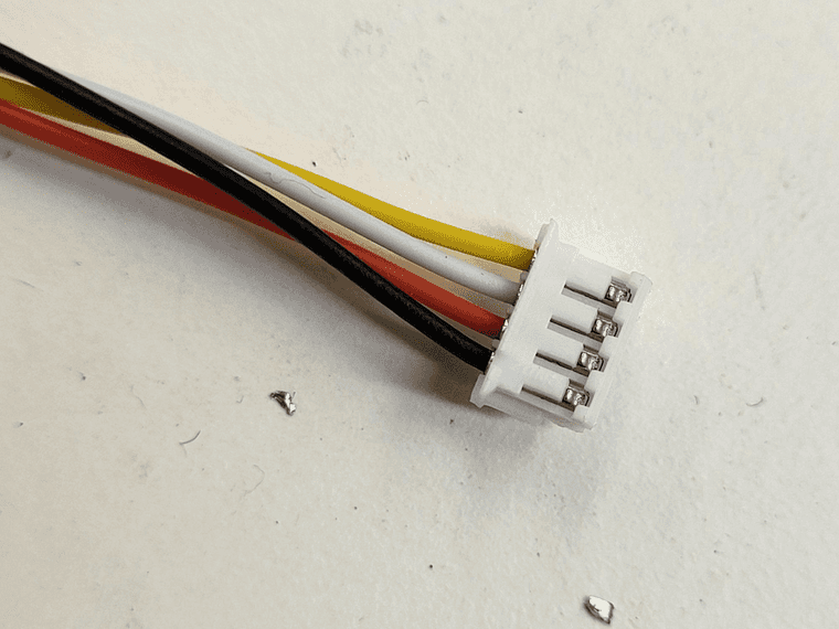
I plan to solder the 4 pin JST-ZH connector with wires (see pic below) that came with the TDB to the wires of the M8 connector since crimping terminals to this would be challenging.
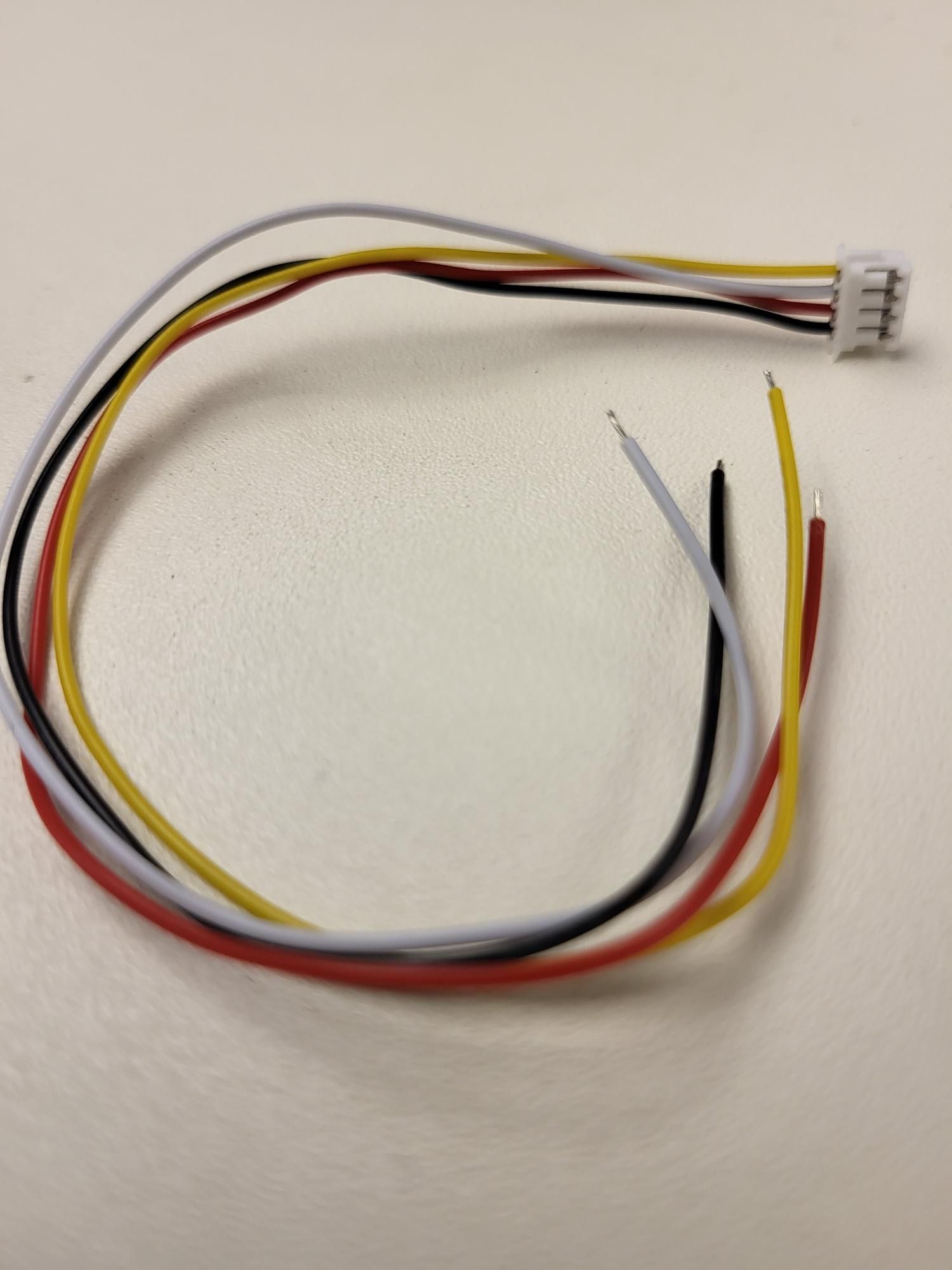
For connecting Roto tool board to TDB as stubs, Does it matter to which of the two pairs of CAN in Tool of TDB I connect to? The XT30(2+2) connector has two CAN wires for CAN_H (yellow) and CAN_L (green). Is the following wiring diagram correct?
I wasn't sure if the pair of CAN wires from XT30(2+2) would go to CAN_x_0-1 or CAN_x_1-2 in 'Tool1" of the TDB
Are CAN_x_0-1 in 'Tool0' and 'Tool1' in TDB internally connected? -
@RockB Yes, this is correct for the 23CL:
As far as I'm aware the 23CL doesn't have specific CAN_H/CAN_L input or output pins, so at the motor end it shouldn't matter which CAN_H pin the wire from the 'Tool 0' (slightly confusingly named) CAN1_H pin connects to, so long as the other CAN_H pin connects back to CAN_H_0-1 on the TDB. The bypass jumpers should be removed for each 'tool #' ouput/input that is wired like this, and the termination jumper on the TDB should only be in place on the last TDB in the CAN chain.
I plan to solder the 4 pin JST-ZH connector with wires (see pic below) that came with the TDB to the wires of the M8 connector since crimping terminals to this would be challenging.
That should be fine.
Does it matter to which of the two pairs of CAN in Tool of TDB I connect to?
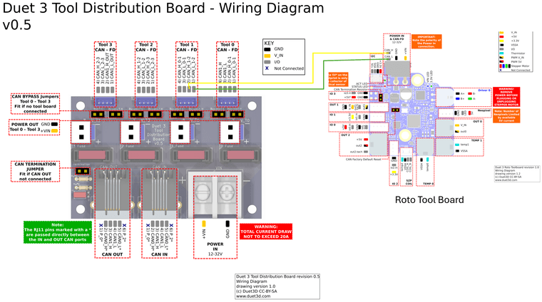
I wasn't sure if the pair of CAN wires from XT30(2+2) would go to CAN_x_0-1 or CAN_x_1-2 in 'Tool1" of the TDBIf you're wiring a stub, and the bypass jumpers are in place, no it doesn't matter which pair you connect the stub to. I just realised that you can connect two stubs to a single 'tool' set of pins on the TDB, one stub to each pair of pins, so you could connect eight toolboards connected as stubs (so long as the bypass jumpers are in place) to a TDB! See the TDB wiring diagram here: https://github.com/Duet3D/Duet3-Tool-Distribution-Board/blob/master/Tool Distribution v0.5/Duet3_Tool_Breakout_Schematic_v0.5.pdf
The same limitations on the lengths of stubs applies, ie maximum length of individual stubs is 1m, total length of all stubs is 5m.Are CAN_x_0-1 in 'Tool0' and 'Tool1' in TDB internally connected?
Yes, in that the CAN bus loops internally from RJ11 CAN IN input CAN1_H/L to T0 header CAN1_H/L (these two pins are confusingly named), then from CAN_H/L_0-1 to T1 CAN_H/L_0-1, and so on. Fitting the bypass jumpers means that the loop out of each 'tool' connector is bypassed, but the pin pairs can still be connected to with stubs.
I'm planning to add some more documentation and diagrams for TDB connections on the page here, because it is quite complicated!
Lastly, when wiring the Roto board, the yellow wire in the pre-wired XT30(2x2) goes to the CAN_H pin, as per your diagram. I haven't traced it to check if it's the top or bottom pin in the XT30 connector, but that's what I've used and it works. If you received cables with other colours, see https://docs.duet3d.com/Duet3D_hardware/Duet_3_family/Duet_3_Roto_Toolboard#can-connection
Hope that helps.
Ian
-
Hi @droftarts Ian, Thank you for the suggestions. I started with a simple test of connecting a single Motor 23CL to TDB 'Tool0'. I am using the same wiring diagram

I see the RED LED of the Motor 23CL blinking rapidly and looking into the documentation on LED error codes, this means that the motor does not have CAN communication with the main board. I have made sure to remove the bypass jumpers for 'Tool0' in TDB and the same power supply is used to power mainboard 6HC and TDB (hence the Motor).
Checking status in DWC using M115 B123 or M122 B123 gives me
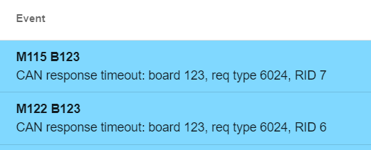
The connections are fairly straightforward. What am I missing here? What can I do to troubleshoot this CAN communication issue?
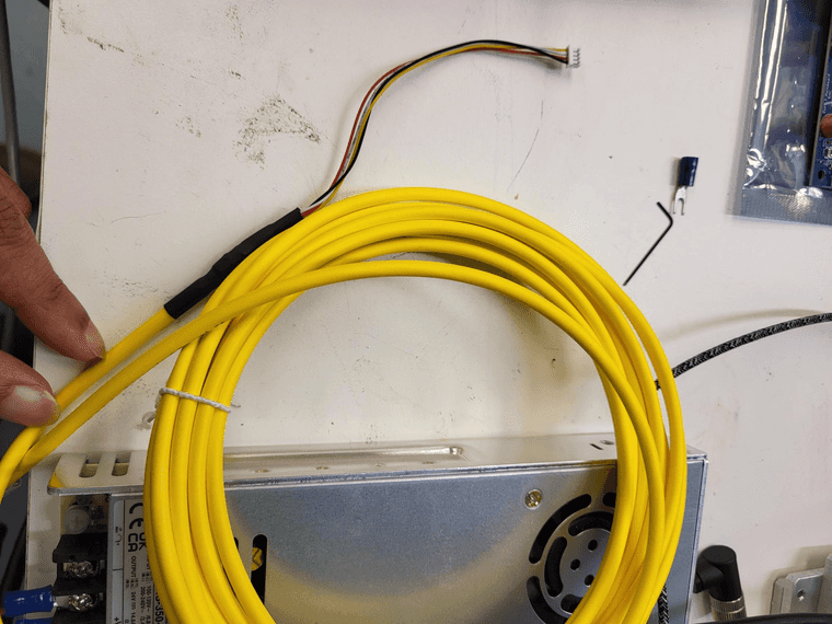
Also, the M8 cable I am using for motor 23CL is 5 meters long and the 4 pin JST-ZH with wires that come with TDB are soldered to the ends of the M8 cable.
link: https://www.automationdirect.com/adc/shopping/catalog/cables_(terminated)/circular_connection_cables/7000-08101-0310500 -
@RockB Have you added
G4 S2at the beginning of config.g? https://docs.duet3d.com/Duet3D_hardware/Duet_3_family/Duet_3_Motor_23CL#startup-timeDouble check the CAN connections. Use a multimeter to check that CAN_H goes to CAN_H, and the same with CAN_L. Check that the cable from the 6HC to the Tool distribution board is wired correctly, too, see https://docs.duet3d.com/en/User_manual/Machine_configuration/CAN_connection#cables
The order of the wires in the RJ11 plugs should be the same both ends of the cable.What version of RRF is the 6HC running? Send M115 and post the response. It could be that the firmware versions are out of sync, which can cause them not to connect. I'm checking how to force a firmware update on the 23CL, but I think you can do it by pressing the CAN reset button, which is between the power and CAN M8 connectors on the motor. You could also try sending
M997 B123. Make sure you have uploaded the 23CL firmware file from the firmware version your 6HC is running; it will be called "Duet3Firmware_M23CL.bin" and should be in the /firmware folder on the SD card, if you're running in standalone rather than SBC mode.Ian
Bed-slinger - Mini5+ WiFi/1LC | RRP Fisher v1 - D2 WiFi | Polargraph - D2 WiFi | TronXY X5S - 6HC/Roto | CNC router - 6HC | Tractus3D T1250 - D2 Eth
-
@droftarts said in Using tool distribution board for multiple Motors 23CL:
@RockB Have you added
G4 S2at the beginning of config.g? https://docs.duet3d.com/Duet3D_hardware/Duet_3_family/Duet_3_Motor_23CL#startup-timeYes. I have added this to the beginning of config.g
I have also attached config.g for reference. config.gDouble-check the CAN connections. Use a multimeter to check that CAN_H goes to CAN_H, and the same with CAN_L. Check that the cable from the 6HC to the Tool distribution board is wired correctly, too, see https://docs.duet3d.com/en/User_manual/Machine_configuration/CAN_connection#cables
The order of the wires in the RJ11 plugs should be the same both ends of the cable.I checked the continuity of the wires using multi-meter. No issues there. I even created a small cable using the M8 connector that came with Motor and a spare 4-pin JST-ZH connector to see if the length of the cable was an issue. Didn't change anything.
I am using the RJ-11 cable that comes with the TDB.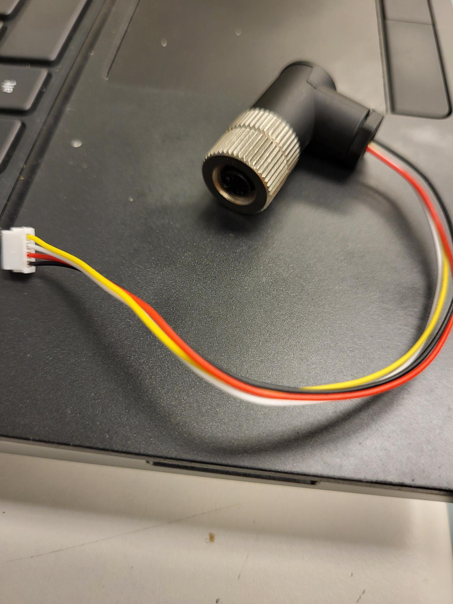
What version of RRF is the 6HC running? Send M115 and post the response.
Running the latest version of RRF 3.5.2
Downloaded the Duet2and3Firmware-3.5.2.zip from the latest release GitHub repository and installed by going to Settings --> Machine Specific --> Install Update in DWCM115 Output below

It could be that the firmware versions are out of sync, which can cause them not to connect. I'm checking how to force a firmware update on the 23CL, but I think you can do it by pressing the CAN reset button, which is between the power and CAN M8 connectors on the motor.
Tried pressing the reset button using a small Allen Key supplied with motor connectors. Nothing changed. The RED led keeps blinking
You could also try sending
M997 B123. Make sure you have uploaded the 23CL firmware file from the firmware version your 6HC is running; it will be called "Duet3Firmware_M23CL.bin" and should be in the /firmware folder on the SD card, if you're running in standalone rather than SBC mode.Sending M997 B123 gives
Also adding M122 output here in case information might be useful
M122
=== Diagnostics ===
RepRapFirmware for Duet 3 MB6HC version 3.5.2 (2024-06-11 17:13:58) running on Duet 3 MB6HC v1.02 or later (standalone mode)
Board ID: 0JD4M-958L1-M24TD-6J1F2-3S46K-K0TFX
Used output buffers: 1 of 40 (18 max)
=== RTOS ===
Static ram: 155360
Dynamic ram: 119688 of which 0 recycled
Never used RAM 70944, free system stack 188 words
Tasks: NETWORK(1,ready,40.3%,157) ETHERNET(5,nWait 7,0.0%,320) HEAT(3,nWait 6,0.0%,353) Move(4,nWait 6,0.0%,335) CanReceiv(6,nWait 1,0.0%,939) CanSender(5,nWait 7,0.0%,334) CanClock(7,delaying,0.0%,346) TMC(4,nWait 6,9.2%,55) MAIN(1,running,49.0%,103) IDLE(0,ready,1.5%,29), total 100.0%
Owned mutexes:
=== Platform ===
Last reset 00:06:30 ago, cause: software
Last software reset at 2024-06-19 15:36, reason: User, Gcodes spinning, available RAM 68056, slot 1
Software reset code 0x0003 HFSR 0x00000000 CFSR 0x00000000 ICSR 0x0044a000 BFAR 0x00000000 SP 0x00000000 Task MAIN Freestk 0 n/a
Error status: 0x00
MCU temperature: min 39.9, current 42.0, max 43.2
Supply voltage: min 24.0, current 24.0, max 24.1, under voltage events: 0, over voltage events: 0, power good: yes
12V rail voltage: min 12.1, current 12.3, max 12.4, under voltage events: 0
Heap OK, handles allocated/used 0/0, heap memory allocated/used/recyclable 0/0/0, gc cycles 0
Events: 0 queued, 0 completed
Driver 0: standstill, SG min n/a, mspos 8, reads 58402, writes 11 timeouts 0
Driver 1: standstill, SG min n/a, mspos 8, reads 58402, writes 11 timeouts 0
Driver 2: standstill, SG min n/a, mspos 8, reads 58402, writes 11 timeouts 0
Driver 3: standstill, SG min n/a, mspos 8, reads 58403, writes 11 timeouts 0
Driver 4: standstill, SG min n/a, mspos 8, reads 58403, writes 11 timeouts 0
Driver 5: standstill, SG min n/a, mspos 8, reads 58403, writes 11 timeouts 0
Date/time: 2024-06-19 16:57:43
Slowest loop: 3.37ms; fastest: 0.07ms
=== Storage ===
Free file entries: 20
SD card 0 detected, interface speed: 25.0MBytes/sec
SD card longest read time 2.4ms, write time 0.0ms, max retries 0
=== Move ===
DMs created 125, segments created 0, maxWait 0ms, bed compensation in use: none, height map offset 0.000, max steps late 0, min interval 0, bad calcs 0, ebfmin 0.00, ebfmax 0.00
no step interrupt scheduled
Moves shaped first try 0, on retry 0, too short 0, wrong shape 0, maybepossible 0
=== DDARing 0 ===
Scheduled moves 0, completed 0, hiccups 0, stepErrors 0, LaErrors 0, Underruns [0, 0, 0], CDDA state -1
=== DDARing 1 ===
Scheduled moves 0, completed 0, hiccups 0, stepErrors 0, LaErrors 0, Underruns [0, 0, 0], CDDA state -1
=== Heat ===
Bed heaters -1 -1 -1 -1 -1 -1 -1 -1 -1 -1 -1 -1, chamber heaters -1 -1 -1 -1, ordering errs 0
=== GCodes ===
Movement locks held by null, null
HTTP is idle in state(s) 0
Telnet is idle in state(s) 0
File is idle in state(s) 0
USB is idle in state(s) 0
Aux is idle in state(s) 0
Trigger is idle in state(s) 0
Queue is idle in state(s) 0
LCD is idle in state(s) 0
SBC is idle in state(s) 0
Daemon is idle in state(s) 0
Aux2 is idle in state(s) 0
Autopause is idle in state(s) 0
File2 is idle in state(s) 0
Queue2 is idle in state(s) 0
Q0 segments left 0, axes/extruders owned 0x0000000
Code queue 0 is empty
Q1 segments left 0, axes/extruders owned 0x0000000
Code queue 1 is empty
=== CAN ===
Messages queued 1959, received 0, lost 0, errs 312351, boc 3918
Longest wait 0ms for reply type 0, peak Tx sync delay 0, free buffers 50 (min 49), ts 1953/0/0
Tx timeouts 0,0,0,0,0,0
=== Network ===
Slowest loop: 6.92ms; fastest: 0.03ms
Responder states: MQTT(0) HTTP(0) HTTP(0) HTTP(0) HTTP(0) HTTP(0) HTTP(0) FTP(0) Telnet(0) Telnet(0)
HTTP sessions: 1 of 8
= Ethernet =
Interface state: active
Error counts: 0 0 0 1 0 0
Socket states: 5 2 2 2 2 0 0 0
=== WiFi ===
Interface state: disabled
Module is disabled
Failed messages: pending 0, notrdy 0, noresp 0
Socket states: 0 0 0 0 0 0 0 0
=== Multicast handler ===
Responder is inactive, messages received 0, responses 0
Any suggestions?
-
@RockB Try powering up the drive with the CAN reset button pressed. Most other Duet expansion boards and toolboards reset their CAN address and request firmware this way.
Ian
Bed-slinger - Mini5+ WiFi/1LC | RRP Fisher v1 - D2 WiFi | Polargraph - D2 WiFi | TronXY X5S - 6HC/Roto | CNC router - 6HC | Tractus3D T1250 - D2 Eth
-
@RockB I think you should post photos of your boards so folks can see exactly how you have the CAN connections wired and how you have the various jumpers set.
-
@droftarts @gloomyandy
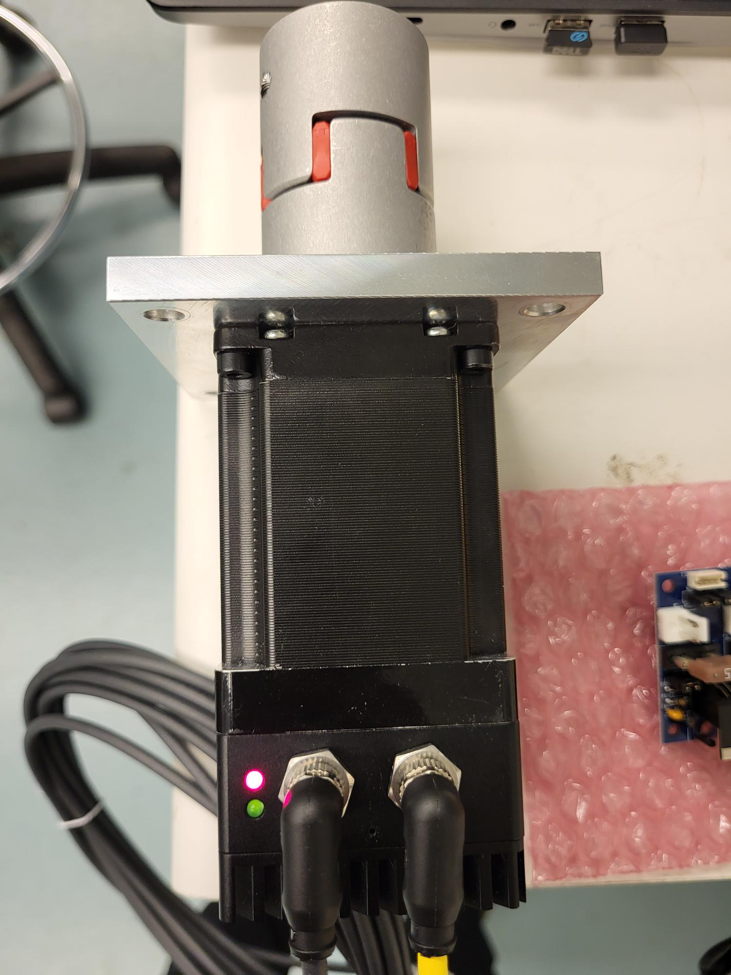
I tried powering on the motor with reset pressed. The lights stop blinking for a brief while, both red and green led flash once, and then after I release pressing the reset, the motor goes to blinking red led.Here is a video: M23CL Reset Video.mp4
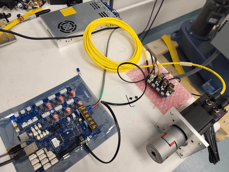
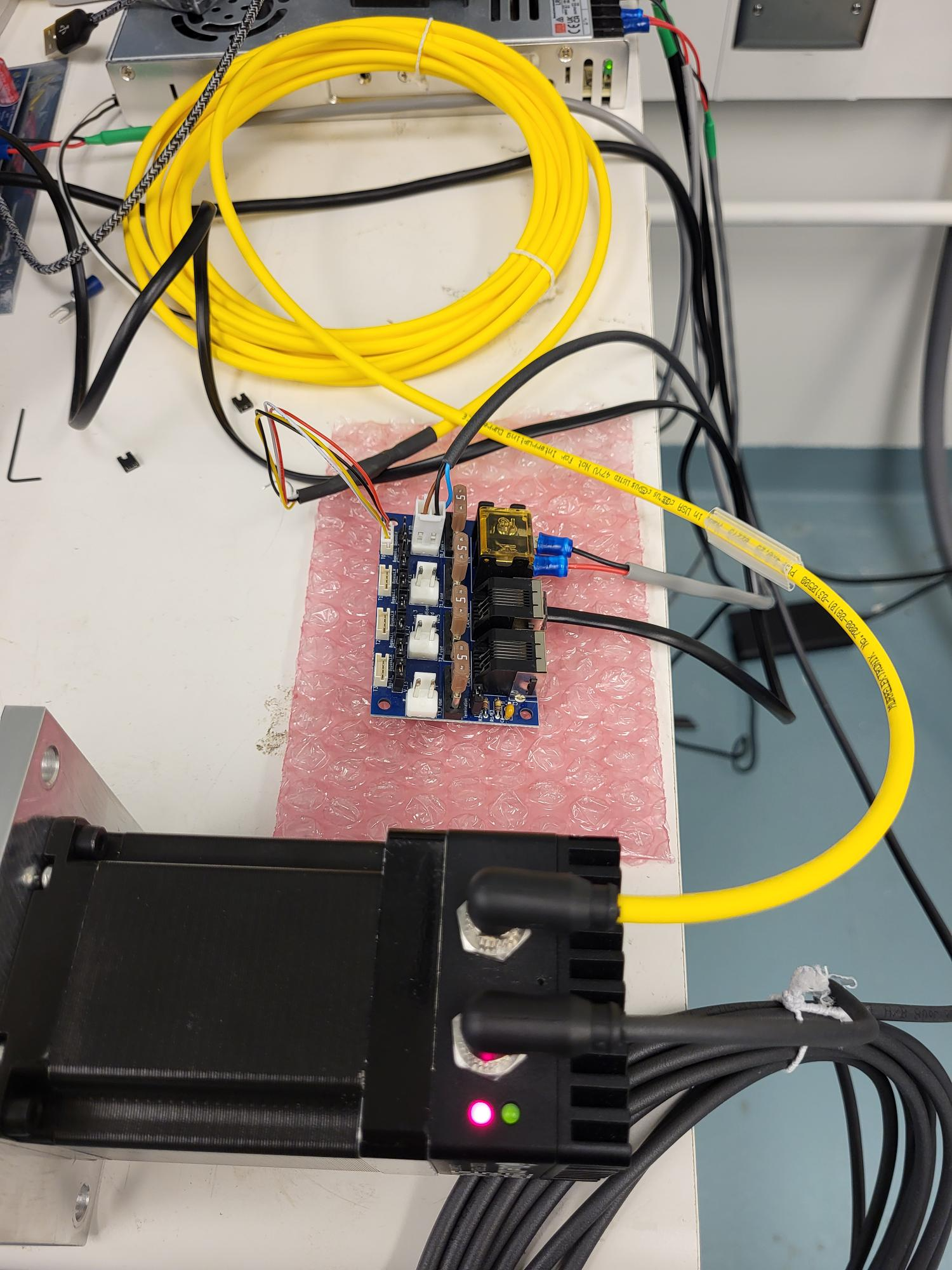
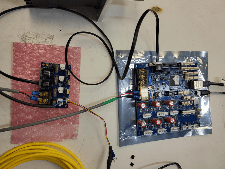
Following are some pictures of my setup. Let me know if any other information is needed to help troubleshoot this issue
-
@RockB Has it always flashed in this pattern, or did it used to flash continuously? Flashing and then a pause generally means the bootloader is reporting a problem; see https://docs.duet3d.com/User_manual/Machine_configuration/CAN_connection#led-behaviour-and-error-codes
In this case, "Bad firmware CRC". This could be caused by an attempted upload. If it continually flashes in this way now, even after a power cycle, I'll have to find out how to recover from it.Ian
Bed-slinger - Mini5+ WiFi/1LC | RRP Fisher v1 - D2 WiFi | Polargraph - D2 WiFi | TronXY X5S - 6HC/Roto | CNC router - 6HC | Tractus3D T1250 - D2 Eth
-
@droftarts It always used to flash red led quickly as seen in my video above. Whenever the motor is powered with reset pressed, it flashes both red and green led once and then reverts back to continuous flashing of red led once the reset is released.
I haven't noticed a pause when red led is blinking. The only pause is when the motor is powered up with reset pressed.
I tested using another motor 23CL (with brake) and I saw the same red led blinking pattern.
Not if this would help, but I checked the contents of the SD card after upgrading to firmware 3.5.2 and uploading a custom RRF firmware for my machine. I saw a firmware folder nested within a main firmware folder. The nested folder contained bin files for 23CL and Tool1RR. While the main firmware folder already had these two bin files along with a lot of other files from Duet2and3Firmware-3.5.2.zip
I guess the nested firmware folder was created from RRF config tool.
Any suggestions on how to recover from this would be appreciated
-
@RockB The folder structure should be as shown here: https://docs.duet3d.com/en/User_manual/RepRapFirmware/SD_card#sd-card-structure
There should be a 'firmware' folder in the root, which is where firmware files are read from. The "Duet3Firmware_M23CL.bin" file should be in that. Make sure you're using the one from the 3.5.2 zip file. Ideally refresh it with a new copy, as it's usually a corrupt firmware file that gives the 'Bad firmware CRC' message.If you have a second firmware folder in the 'sys' folder, you can safely delete that.
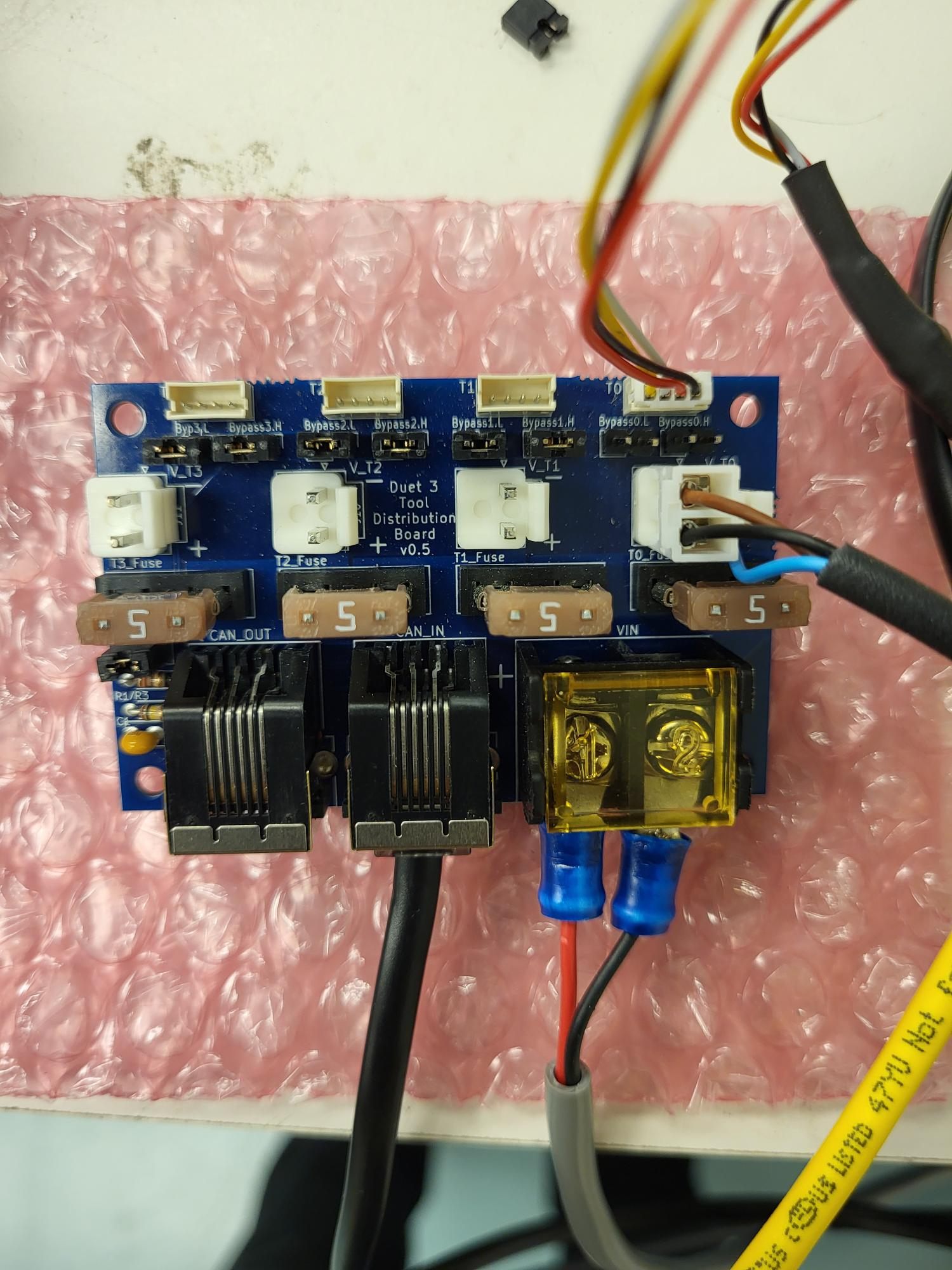
As far as I can tell, your wiring looks correct, with bypass jumpers removed from the Tool Distribution board for the connected tool, and the CAN termination jumper is in place. But I can't see the RJ11 cable between the Duet and the TDB, and I can't see the CAN wiring at the motor end. There's still a possibility that it's a wiring issue.
When you press the reset button on the 23CL, does anything show up in the console of DWC? If it is requesting firmware, I think you should get a message there.
uploading a custom RRF firmware for my machine
You have modified and compiled RRF for yourself? If so, please revert to the released version until we get this issue sorted out.
Ian
Bed-slinger - Mini5+ WiFi/1LC | RRP Fisher v1 - D2 WiFi | Polargraph - D2 WiFi | TronXY X5S - 6HC/Roto | CNC router - 6HC | Tractus3D T1250 - D2 Eth
-
@droftarts said in Using tool distribution board for multiple Motors 23CL:
@RockB The folder structure should be as shown here: https://docs.duet3d.com/en/User_manual/RepRapFirmware/SD_card#sd-card-structure
There should be a 'firmware' folder in the root, which is where firmware files are read from. The "Duet3Firmware_M23CL.bin" file should be in that. Make sure you're using the one from the 3.5.2 zip file. Ideally refresh it with a new copy, as it's usually a corrupt firmware file that gives the 'Bad firmware CRC' message.I have copied the fresh contents from 3.5.2 zip file to the firmware folder on SD card. (only the .bin files)
If you have a second firmware folder in the 'sys' folder, you can safely delete that.
The second firmware folder was actually within the main 'firmware' folder. I have deleted this second firmware folder.
Tested again after these changes. Same issue with fast blinking red led on motor.
As far as I can tell, your wiring looks correct, with bypass jumpers removed from the Tool Distribution board for the connected tool, and the CAN termination jumper is in place. But I can't see the RJ11 cable between the Duet and the TDB, and I can't see the CAN wiring at the motor end. There's still a possibility that it's a wiring issue.
Here are some more pictures and wiring diagram:
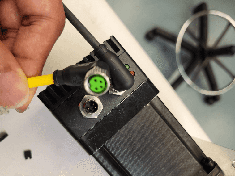
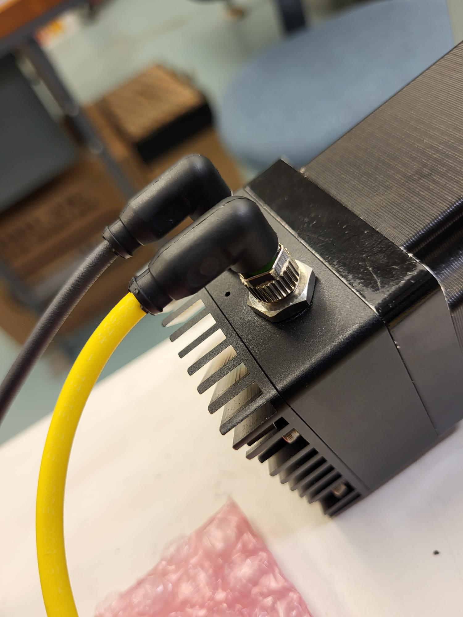
Soldering connection for coneecting 4-pin M8 cable with 4 pin JST-ZH cable:
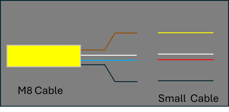
Manufacturer wiring diagram for M8 cable:
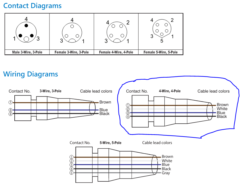
When you press the reset button on the 23CL, does anything show up in the console of DWC? If it is requesting firmware, I think you should get a message there.
Nope. I am not getting any message on DWC after I press the reset button.
uploading a custom RRF firmware for my machine
You have modified and compiled RRF for yourself? If so, please revert to the released version until we get this issue sorted out.
Apologies, I meant I have used RRF config tool to create a custom config for my machine. In the first config I created had multiple 23CLs and Tool1RRs called out in the config.g; however only one 23CL was connected to TDB for testing. I did get some errors like the Heater not found and so on since no Tool1RRs were connected at that time. I am not sure if this triggered the condition or had anything to do with it. One of my replies above contains the config.g file where I have commented out other axes, extruders, fans and tools while only 23CL is mapped to Z axis for testing.
Just to check the CAN connections, does it matter if a config.g file is present?
-
@RockB Thanks, as far as I can tell the motor wiring looks to be correct.
Could you wire up a Roto board, and see if you can get that to connect? It only needs power, and the two CAN wires connected to two of the pins on the TDB. Leave the bypass jumpers in place on the TDB, for the tool output you connect it to. Remove the 23CL CAN wiring, and put the bypass jumpers back in place there, too.
If the colours of the wires in both ends of the RJ11 cable are visible, check they are in the same order.
Ian
Bed-slinger - Mini5+ WiFi/1LC | RRP Fisher v1 - D2 WiFi | Polargraph - D2 WiFi | TronXY X5S - 6HC/Roto | CNC router - 6HC | Tractus3D T1250 - D2 Eth
-
@RockB said in Using tool distribution board for multiple Motors 23CL:
Just to check the CAN connections, does it matter if a config.g file is present?
It helps in that it starts up the network, but you don't need anything configured in config.g to check a board is on the CAN bus.
Ian
-
@RockB said in Using tool distribution board for multiple Motors 23CL:
It always used to flash red led quickly as seen in my video above. Whenever the motor is powered with reset pressed, it flashes both red and green led once and then reverts back to continuous flashing of red led once the reset is released.
How fast is it flashing? Once a second means it is connected to the main board and running normally. Several times a second with no pauses means it doesn't have communication with the main board. Several times with pauses means it is reporting an error code.
-
@droftarts @dc42
I finally figured out this issue. I swapped out TDB with a new one and things started working. The red LED now blinks every second showing the Motor can communicate with the mainboard. I also tried wiring the roto toolboard to the same TDB as the stub and that also worked well.
I can communicate to both devices using M122 and M115.The TDB was purchased recently from Filastruder. Any thoughts on why this would go bad?
-
@RockB The TDB is a pretty simple, passive, device, so there's not much to go wrong. It's possible there's a soldering fault on it, I suppose. Or maybe the pins in the CAN connector is misaligned. Can you take a picture of both sides of the board and post them?
Ian
Bed-slinger - Mini5+ WiFi/1LC | RRP Fisher v1 - D2 WiFi | Polargraph - D2 WiFi | TronXY X5S - 6HC/Roto | CNC router - 6HC | Tractus3D T1250 - D2 Eth