LED VORON WS2812E
-
Good evening everyone,
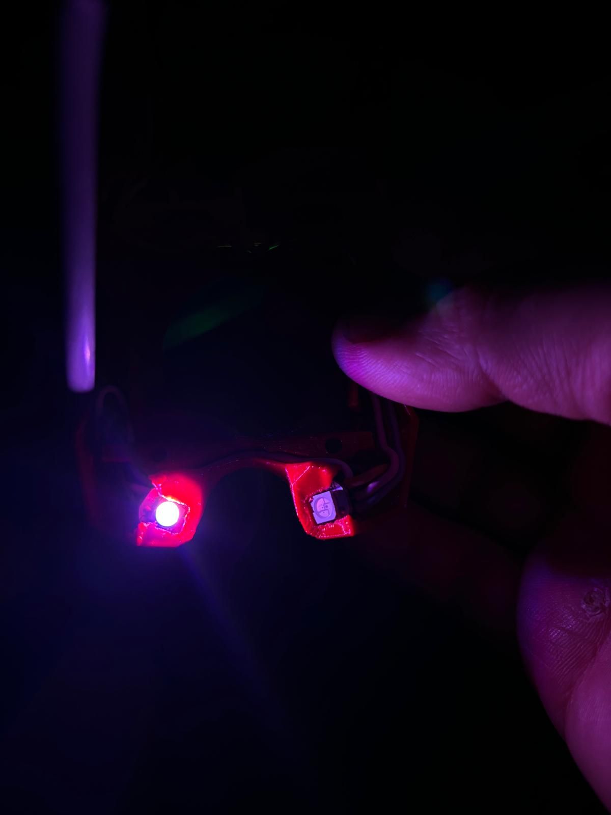
I have a problem configuring the LEDs. I have an original toolboard v1.3, and I have connected them to IO_0. There are 3 LEDs, and I have attached a photo. I tried to write the .config file with the following lines:
; Led Neopixel
M950 P0 C"121.io0.out" Q500             ; Configura il pin di uscita per i NeoPixel con frequenza PWM 500Hz
M150 X0 Q3000000 D3                     ; Abilita il controllo dei LED NeoPixel con una velocità dati di 3MHz e 3 LED
One of the 3 LEDs is not working, one is green and one is white. I don't understand why. Additionally, I am getting this error:
Can anyone help me solve this problem?

Thanks in advance! -
What firmware version?
There's a known bug in 3.5.1 which makes the first LED green, but I don't recall it being reported on a toolboard. https://github.com/Duet3D/RepRapFirmware/issues/996
If it is 3.5.1 your M950 and M150 config lines look very wrong. M950 shoudl have E0 not P0, Q should be 3000000 (probably), M150 should not have Q or D and should have some colour definitions.
-
@nico-rast That does not look like the correct configuration for a Neopixel. You need to use the E parameter to M950 when configuring the port for use with a Neopixel. See the following guide: https://docs.duet3d.com/User_manual/Connecting_hardware/IO_Neopixel_DotStar
But we really need to know what version of RRF you are using to be able to provide more accurate information.
-
@gloomyandy I have updated all the boards (MB 6HC + Toolboard 1LC v1.3 + Raspberry Pi4) to RRF 3.5.1.
I searched online a bit and tried to do the programming with ChatGPT") . I had seen something in the forum and it seemed to be somewhat similar
. I had seen something in the forum and it seemed to be somewhat similar -
@nico-rast For RRF 3.5.1, try:
; Led Neopixel
M950 E0 C"121.io0.out" U3 T1
M150 E0 R255 U255 B255 S3
It is important to use U3 with M950, to define the number of LEDs, especially on a toolboard where memory is limited. Be aware of the current draw of your LEDs (usually around 60mA for each LED when all on), particularly if connected to 5V on the toolboard, which has a total 5V current limit of 300mA; see https://docs.duet3d.com/Duet3D_hardware/Duet_3_family/Duet_3_Toolboard_1LC#operating-limits.
Ian
Bed-slinger - Mini5+ WiFi/1LC | RRP Fisher v1 - D2 WiFi | Polargraph - D2 WiFi | TronXY X5S - 6HC/Roto | CNC router - 6HC | Tractus3D T1250 - D2 Eth
-
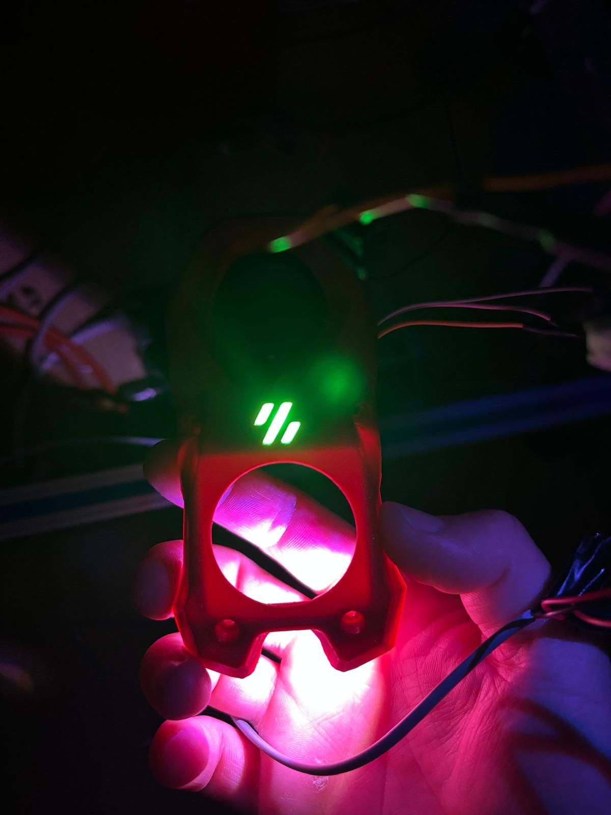
@droftarts Thanks Ian, that works.
All leds now are white. i tried some M150 to change color, but it not works. Surely it's my fault!Toolboard connection:
DRIVE0 --> E0
IN_0 --> 3 leds
T0 --> original thermistor E3d
OUT0 --> Resistor 24V
OUT1 + OUT2 --> FAN 24 V
IO_1 or IO_2 --> klicky probeI can't understand why it's a bit hot. MCU temperature: min 46.3C, current 50.8C, max 50.9C.
-
@nico-rast I have the same Stealthburner configuration as yours (my hardware is a little diffrent as im not using a raspberry Pi I only have the Duet2 wifi and the Duex5 and they run everything) my leds are controlled with the following code if it help:
; Code to start Stealthburner LEDS

M150 X4 ;Set the LED type to WRGB Leds
M150 R255

M150 R255 P255 S1 F1 ;Set the first LED to Red full brightness and continue programming strip (F1)
M150 W255 P255 S2 ;Set next two LEDS to white and complete strip programming
And to turn them off:
; Code to reset the full Stealthburner LEDS to 0 which is off

M150 W0 P0 S3
I also have a few macros to control just the centre LED to switch colours depending on the action its doing (so blue when in bed levelling red if there is a problem etc) and that code looks like this (one macro per colour)
; Code to start Stealthburner LEDS

M150 X4 ;Set the LED type to WRGB Leds
;M150 R255

M150 B255 P150 S1 F1 ;Set the first LED to Blue full brightness and continue programming strip (F1)
M150 W0 P0 S2 ;Set next two LEDS to off and complete strip programming
Its the same code as before apart from the colour and the final two leds are deactivated.
I have also added (or are in the process of adding ) led strips the the chassis to change colour to match the operation or just to light the enclosure these are all powered from the Duex 5 additional heaters, the code in the config file to do this is :
;LED Strip control via heater channels ----------------------------

; M42 Px S0 to S1 controls brightness (Voltage 1 = Max 0.1 min)
; mix strip colours to build diffrent colours

M950 P10 C"duex.e2heat" Q500  ;assign to P6 WHITE
M950 P11 C"duex.e3heat" Q500  ;assign to P7 BLUE
M950 P12 C"duex.e4heat" Q500  ;assign to P8 RED
M950 P13 C"duex.e5heat" Q500  ;assign to P9 GREEN
M42 P10 S0					;Turn WHITE LED strip off
M42 P11 S0					;Turn BLUE LED strip off
M42 P12 S0					;Turn RED LED strip off
M42 P13 S0					;Turn GREEN LED strip off
These are just WRGB strips so not individually addressable
-
@nico-rast Hi, sorry for the delay coming back to this. I have set up an LED strip on my 1LC running RRF 3.5.2, and can confirm your findings that all LEDs turn on white, no matter the M150 command that is sent. I'll check with @dc42 and raise an issue on Github, and hopefully this will be fixed in the next release. Incorrect LED lighting is usually as a result of a timing issue sending the correct PWM signals to the LEDs.
@Chaos3d Thanks, but different hardware, so not a comparable issue. We went through fixing the Duet 2 LED output in the 3.5 release candidates. See https://github.com/Duet3D/RepRapFirmware/issues/969
Ian
-
@Chaos3d Thank you very much for your explanation, but I believe it is not suitable for my hardware.
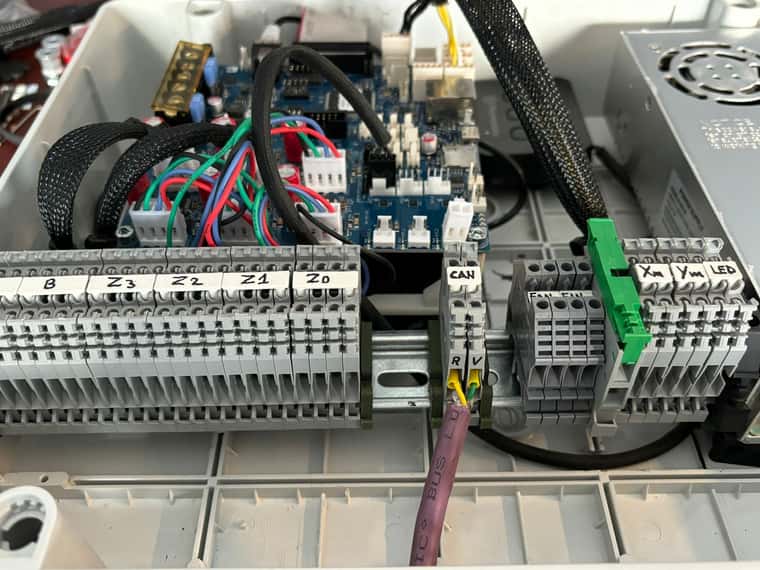
@droftarts no worries, Ian, there are no problems. The printer is still under construction, I won't stop because of the LEDs!! I have connected them to the IO8 port of my 6HC for safety. There is one more thing I didn't understand. I need to make a CAN cable about 2.5 meters long from the toolboard to the mainboard. I am using a specific cable for the CAN connection; it is shielded, twisted, and very thick.!!
Immagine WhatsApp 2024-06-26 ore 18.59.12_156a208d.jpgI have also kept the CAN terminals separate, as you can see in the photo, to avoid interference. Could this work?
Thanks
Nico
-
@nico-rast said in LED VORON WS2812E:
I have connected them to the IO8 port of my 6HC for safety.
IO8 isn't PWM capable. Use IO4, IO5 or IO7, or the dedicated Dotstar/Neopixel ouput, if you want them to work on the 6HC. Sorry, that's wrong, it's any pin that supports a digital output. But you can use the Dotstar/Neopixel ouput, too. See https://docs.duet3d.com/en/User_manual/Connecting_hardware/IO_Neopixel_DotStarThere is one more thing I didn't understand. I need to make a CAN cable about 2.5 meters long from the toolboard to the mainboard. I am using a specific cable for the CAN connection; it is shielded, twisted, and very thick.!!
Thicker wires usually have lower resistance/impedance. Ideally, CAN bus uses 2 X 24AWG twisted pair with an impedence of 120ohms. The wires can be shielded, but generally it's not necessary. See https://docs.duet3d.com/en/User_manual/Machine_configuration/CAN_connection#cables
I have also kept the CAN terminals separate, as you can see in the photo, to avoid interference. Could this work?
That should be fine.
Ian
-
@droftarts I use 3 dotstar for the stealthburner extruder, so should be fine.
I checked the resistance of the wire and i get about 0.4ohms over 3 meters (the wire has a section of 0.25mm2).
Can i put a 120 ohm resistor in series with the wire?
This usually done in industrial machinery.
I noticed a GND_SHIELD connector, can I use it to connect the cable shields?
All my cables are shielded.Thanks
Nico
-
@nico-rast 0.25mm^2 is the same as 24AWG, so I'd just try it. Impedance isn't quite the same thing as resistance, but I'm not sure how you convert between them.
The GND_SHIELD is meant for shielded Ethernet, but I don't see a problem connecting other shield wires to it.
Ian
-

