@oliof
Thanks man IT WORKS!!!!
Best posts made by nico.rast
Latest posts made by nico.rast
-
RE: Toolboard 1LC v1.3 Phase A error.posted in General Discussion
@droftarts i found this: TDK MLK0603L3N0ST000.
Can be suitable? I know a man that repair smd elettronics but he needs the pieces... -
RE: Toolboard 1LC v1.3 Phase A error.posted in General Discussion
@droftarts Hi Ian, after searching online for the replacement part, it turns out to be a filter—my mistake for not checking earlier! I haven't tried soldering it because I'm worried about touching nearby components and potentially causing more damage. Is there any way to get the exact part number for this component? I found something online, but you know, if it's not an exact match, I might make things worse.
-
RE: Toolboard 1LC v1.3 Phase A error.posted in General Discussion
Some news,
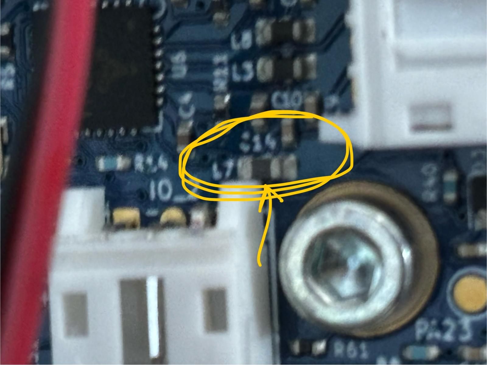 .
.This resistor (L7) doesn’t seem to be soldered properly. When it makes contact, everything works perfectly, but when it moves due to vibrations, the extruder motor reports that Phase A is interrupted.
-
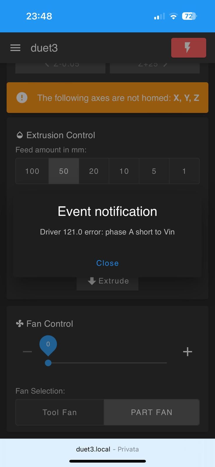
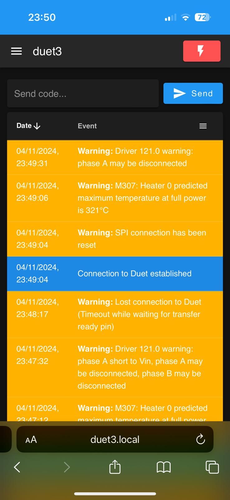
Toolboard 1LC v1.3 Phase A error.posted in General Discussion
Good evening guys, sorry, I think I’ve broken the toolboard :(. Is there anyone who does repairs? I’d rather not buy a new one.
A pin came loose while the printer was on, and it hasn’t worked since then. I tried with two different motors, a Sibor 14st20-1004A following the motor’s color code, and another stepper. Both give me the same error.
Thanks
-
RE: VORON 2.4 A/B STEPPER PROBLEMSposted in Duet Hardware and wiring
@droftarts said in VORON 2.4 A/B STEPPER PROBLEMS:
Hi Ian,
thanks for the response. I didn't notice that there are two steps for the Z axis; one should have been Z and the other E. As for the motors, I currently had these at home and tried them out. I started with a current of 1A and increased it gradually for testing, and it ended up at 2A. Anyway, I will replace them soon with NEMA17 SUPER POWER (42STH48-2804AH). I'll try lowering the speed settings and see if anything moves. The command I sent was always G91 G1 H2 X10 F3000 G90, but I just copied the G1 part, etc.Thanks
Nico -
VORON 2.4 A/B STEPPER PROBLEMSposted in Duet Hardware and wiring
Good evening everyone!
I am finalizing my custom VORON printer, and I am testing the various motors to set everything up correctly. As for the Z-axis with 4 motors, I managed to get it working without any problems; on the first try, the motors responded well (Nema 23). However, I have been struggling for a couple of hours to understand why the motors on the X and Y axes are not responding. I have checked the wiring multiple times, and there seem to be no issues, although the console shows the message "Warning: Driver 0.5 warning: phase A may be disconnected." I changed the driver to see if it was damaged, but the error persists. I am attaching a video of how the motor behaves; both X and Y do the same. I am sending this Gcode "G1 H2 X10 F3000".
Video WhatsApp 2024-07-12 ore 00.23.02_86f62abc.mp4 when i send G1 H2 X10 F3000
Video WhatsApp 2024-07-12 ore 00.17.41_3fb4bcf2.mp4 This happens when the motor is at rest, that is, when it has finished the Gcode just sent.RRF 3.5.2 DUET 6HC SBC MODE.
Here's my configuration file.
G4 S2
G90                                                             ; absolute coordinates...
M83                                                             ; relative extruder moves
M669 K1                                                         ; Select CoreXY mode
M564 S1 H1                                                      ; Forbid axis movements when not homed
M290 R0 S0                                                      ; reset babystepping
;
; ---------- DRIVES MAPPINGS ----------
;
;       Rear
;	| Z1 | Z2 |
;	-----+-----
;	| Z0 | Z3 |
;	-----+-----
;	   Front
;
M584 X2 Y5 Z0:1:3:4 E121.0                                      ; set drive mapping
M569 P0 S0                                                      ; Z0 motor FL goes backwards
M569 P1 S1                                                      ; Z1 motor RL goes forwards
M569 P3 S0                                                      ; Z2 motor RR goes backwards
M569 P4 S1                                                      ; Z3 motor FR goes forwards
M569 P2 S1                                                      ; A motor goes forwards
M569 P5 S1                                                      ; B motor goes forwards
M569 P121.0 S0                                                  ; E1 motor Extruder goes backwards (scheda 1LC porta 121)
M671 X552:552:-55:-55 Y930:-72:-72:930 S15         ; Define Z belts locations (Z0=Front_Left Z1, Z2, Z3...ecc) S15=mm di correzione massima

; Motor Idle Current Reduction
M906 I30 ; set motor current idle factor
M84 S30 ; set motor current idle timeout

; Axes
M350 X32 Y32 Z32 E16 I1 ; configure microstepping with interpolation
M906 X2000 Y2000 Z2400 ; set axis driver currents
M92 X400 Y400 Z160 Z324 ; configure steps per mm
M208 X0 Y0 Z0 S1 ; set minimum axis limits
M208 X510 Y950 Z350 S0  ; set maximum axis limits
M566 X100 Y100 Z12 ; set maximum instantaneous speed changes (mm/min)
M203 X72000 Y72000 Z48000 ; set maximum speeds (mm/min)
M201 X1000 Y1000 Z1000 ; set accelerations (mm/s^2)

; Extruders
M584 E121.0 ; set extruder mapping
M350 E16 I1 ; configure microstepping with interpolation
M906 E700 ; set extruder driver currents
M92 E735 ; configure steps per mm
M566 E120 ; set maximum instantaneous speed changes (mm/min)
M203 E3600 ; set maximum speeds (mm/min)
M201 E250 ; set accelerations (mm/s^2)
M200 D1.75 S1 ; VOLUMETRIC FLOW

; Probes
M558 K0 P8 C"121.io1.in" H5 F120 T6000 ; configure unfiltered digital probe via slot #0
G31 P500 X0 Y0 Z0.7 ; set Z probe trigger value, offset and trigger height

; Accelerometers
M955 P121.0 I54 ; configure accelerometer on board #121

; Led Neopixel
M950 E0 C"Io8.out" U3 T1
M150 E0 R255 U255 B255 S3

; Endstops
M574 X1 P"io0.in" S1 ; configure X axis endstop
M574 Y1 P"io1.in" S1 ; configure Y axis endstop
M574 Z1 S2 ; configure Z axis endstop

; Mesh Bed Compensation
M557 X25:475 Y25:925 S40:40 ; define grid for mesh bed compensation

; Sensors
M308 S0 P"temp0" Y"thermistor" A"Heated Bed" T100000 B4725 C7.06e-8 ; configure sensor #0
M308 S1 P"121.temp0" Y"thermistor" A"Nozzle" T100000 B4725 C7.06e-8 ; configure sensor #1

; Heaters
M950 H0 C"out0" T0 ; create heater #0
M143 H0 P0 T0 C0 S140 A0 ; configure heater monitor #0 for heater #0
M307 H0 R2.43 D5.5 E1.35 K0.56 B1 ; configure model of heater #0
M950 H1 C"121.out0" T1 ; create heater #1
M143 H1 P0 T1 C0 S350 A0 ; configure heater monitor #0 for heater #1
M307 H1 R2.43 D5.5 E1.35 K0.56 B0 ; configure model of heater #1

; Heated beds
M140 P0 H0 ; configure heated bed #0

; Fans
M950 F0 C"121.out2" ; create fan #0
M106 P0 S0 L0 X1 B0.1 ; configure fan #0
M950 F1 C"121.out1" ; create fan #1
M106 P1 S0 B0.1 H1 T45 ; configure fan #1

; Tools
M563 P0 D0 H1 F0:1 ; create tool #0
M568 P0 R0 S0 ; set initial tool #0 active and standby temperatures to 0C

T0

code_text
Thanks!
UPDATE 12.07.24
I switch M669 parameters in K0, just to try driver and motors. They works without any issues.
I can't understand why! -
RE: LED VORON WS2812Eposted in Tuning and tweaking
@droftarts I use 3 dotstar for the stealthburner extruder, so should be fine.
I checked the resistance of the wire and i get about 0.4ohms over 3 meters (the wire has a section of 0.25mm2).
Can i put a 120 ohm resistor in series with the wire?
This usually done in industrial machinery.
I noticed a GND_SHIELD connector, can I use it to connect the cable shields?
All my cables are shielded.Thanks
Nico
-
RE: LED VORON WS2812Eposted in Tuning and tweaking
@Chaos3d Thank you very much for your explanation, but I believe it is not suitable for my hardware.
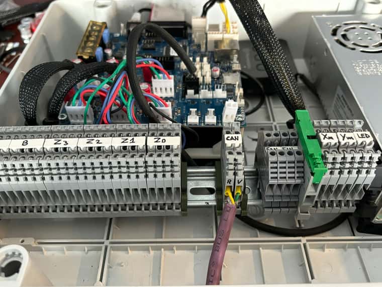
@droftarts no worries, Ian, there are no problems. The printer is still under construction, I won't stop because of the LEDs!!") I have connected them to the IO8 port of my 6HC for safety. There is one more thing I didn't understand. I need to make a CAN cable about 2.5 meters long from the toolboard to the mainboard. I am using a specific cable for the CAN connection; it is shielded, twisted, and very thick.!!
I have connected them to the IO8 port of my 6HC for safety. There is one more thing I didn't understand. I need to make a CAN cable about 2.5 meters long from the toolboard to the mainboard. I am using a specific cable for the CAN connection; it is shielded, twisted, and very thick.!!
Immagine WhatsApp 2024-06-26 ore 18.59.12_156a208d.jpgI have also kept the CAN terminals separate, as you can see in the photo, to avoid interference. Could this work?
Thanks
Nico