Duet 3 Mini 5+ with Canbus boards.
-
My setup is:
Duet 3 Mini 5+
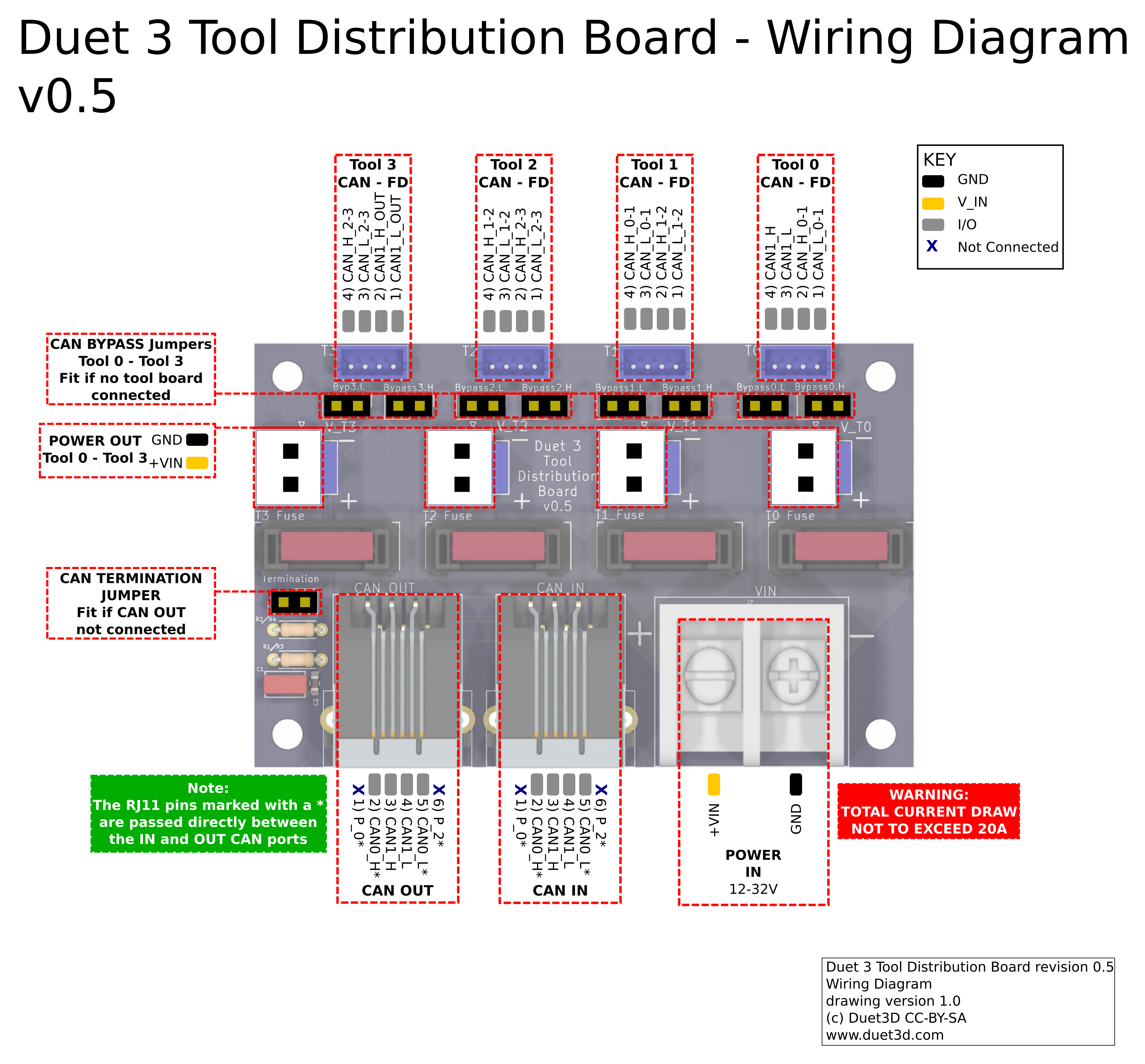
Duet 3 Tool Distribution Board
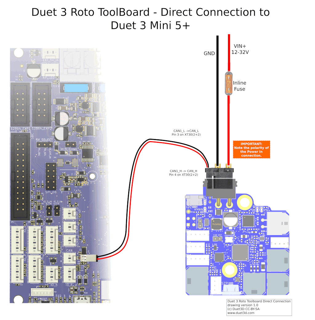
Duet 3 Roto Toolboard (X2 for two tools as of now)I connected the Can 1 H and Can 1 L from the two center pins on the distribution board IN RJ11 plug to
the Can L and Can H pins of the CanFD pins on the Mini 5+I connected two pins of the Tool0 4 pin connector on the Distribution board to the two pins on the roto toolboard (started with only one board to hopefully get it working first)
The pins I used were the confusingly named pins 3 and 4 of connector V-T0
They are labeled as Can1_H (Pin 4) and Can 1_L (Pin 3)I am trying to get my head around the labels on these connectors, and which bypass jumpers to install or remove.
Could someone please explain what these labels mean, which to use, and which jumpers to install for a two tool setup?
Do I have to worry about Can addresses? If so, what is the procedure and recommended addresses?
Do I need to update the firmware on either the Distribution board or the Tool board?
If so, how to check them?A wiring diagram would be helpful for all three components and their CAN FD details. It is hard to determine which pins to connect to corresponding pins on the other boards from the pinout diagrams provided.
Thanks,
JohnP.S. I'm attempting this upgrade while at MRRF2024
-
@j-pickens I suggest you fit all the jumpers on the distribution board except the termination jumper. Connect one Roto Tool board to any pair of CANL and CANH pins on the distribution board and fit the termination jumper on the tool board. Then you should be able to connect to it at its default address (121 AFAIR).
When you have that working, change the CAN address of that tool board, restart and make sure you can connect to it at the new address.
Then connect the second tool board to any pair of CANL and CANH pins on the distribution board. Do not fit the termination jumper to that one. You should be able to access it at its default address again, and then I suggest you change it to a different address.
In general, when you have more than one board with the same default CAN address in a system, you should change the addresses of all of them.
Duet WiFi hardware designer and firmware engineer
Please do not ask me for Duet support via PM or email, use the forum
http://www.escher3d.com, https://miscsolutions.wordpress.com -
@dc42 I attached my toolboard CAN lines directly to the Mini5+. The red LED on the toolboard flashes slowly in sync with the main board, so it appears to be communicating. How do I interrogate the bus to show the address of the toolboard? I assume that its address is the default 121, but I tried to set my config.g to assign Tool 0 to P121 and it does not seem to find it. I get error codes for not finding Canbus devices as shown:
6/23/2024, 11:27:22 AM CAN response timeout: board 61, req type 6042, RID 10
CAN response timeout: board 62, req type 6042, RID 11
CAN response timeout: board 63, req type 6042, RID 12
6/23/2024, 11:27:19 AM CAN response timeout: board 50, req type 6042, RID 8
CAN response timeout: board 51, req type 6042, RID 9
6/23/2024, 11:27:17 AM CAN response timeout: board 51, req type 6043, RID 6
CAN response timeout: board 50, req type 6043, RID 7
6/23/2024, 11:27:15 AM CAN response timeout: board 50, req type 6042, RID 4
CAN response timeout: board 51, req type 6042, RID 5
6/23/2024, 11:27:13 AM CAN response timeout: board 50, req type 6042, RID 2
CAN response timeout: board 51, req type 6042, RID 3 -
@j-pickens you can send M115 B121 to check that the tool board is there and what firmware version it is running, or M122 B121 to get a full diagnostic report.
Don't try to change the CAN addresses in config.g. Do it manually.
In config.g make sure you have a delay command such as G4 S2 before the first command that refers to a tool board.
Duet WiFi hardware designer and firmware engineer
Please do not ask me for Duet support via PM or email, use the forum
http://www.escher3d.com, https://miscsolutions.wordpress.com -
@dc42 You see, here is a big problem with Duet and Canbus.
You just told me to use M122 B121 to get a full Canbus report.
There is nowhere on your search pages, even the Duet Reprapfirmware GCode dictionary to find these codes.
If I hit the search bar while in the dictionary, and I search "Can" "Can-FD" or "Canbus" I get only 2 links to the Gcode dictionary. Now since you told me to use M122, I can search for it. But not knowing the Canbus codes, how am I supposed to find them?The two hits come up as M952 and M953. There appears to be no guide to Canbus here with a technical outline of how to set up and program these boards. Your documentation says things like:
"Typically, the CAN bus is wired in a daisy-chain-style between boards. At one end will be the mainboard, with the CAN bus connecting to each subseqent board."
Nothing specific for your products with pinouts and wiring diagrams for the Main Board/Distribution Board/Multiple Tool Boards. I still have absolutely no idea how to wire your distribution board based upon the cryptic pin labels in your diagram up top of my post, which termination jumpers are needed, and which bypass jumpers to use.
This is getting very frustrating.
-
@dc42 Here is the response from: M122 B121
CAN response timeout: board 121, req type 6024, RID 22I am currently wired Can H to Can H and Can L to Can L with a twisted pair between the CAN header on the Mini 5+ and the first Revo Roto Toolboard. The power to the Toolboard is on, the red activity light is blinking fast, not in sync withe the Mini 5+, and the termination jumper is installed on the Toolboard.
-
@j-pickens Can you have a look at the soldering on the back of the Tool Distribution Board? We just found another board that has solder bridges on the CAN pins. See https://forum.duet3d.com/post/340940
Thanks for your feedback. I do need to add a bit more to the documentation about the TDB. Wiring CAN stubs to it is something quite recent; before boards like the 1LC had a cable that used all four pins, and wiring was clearer.
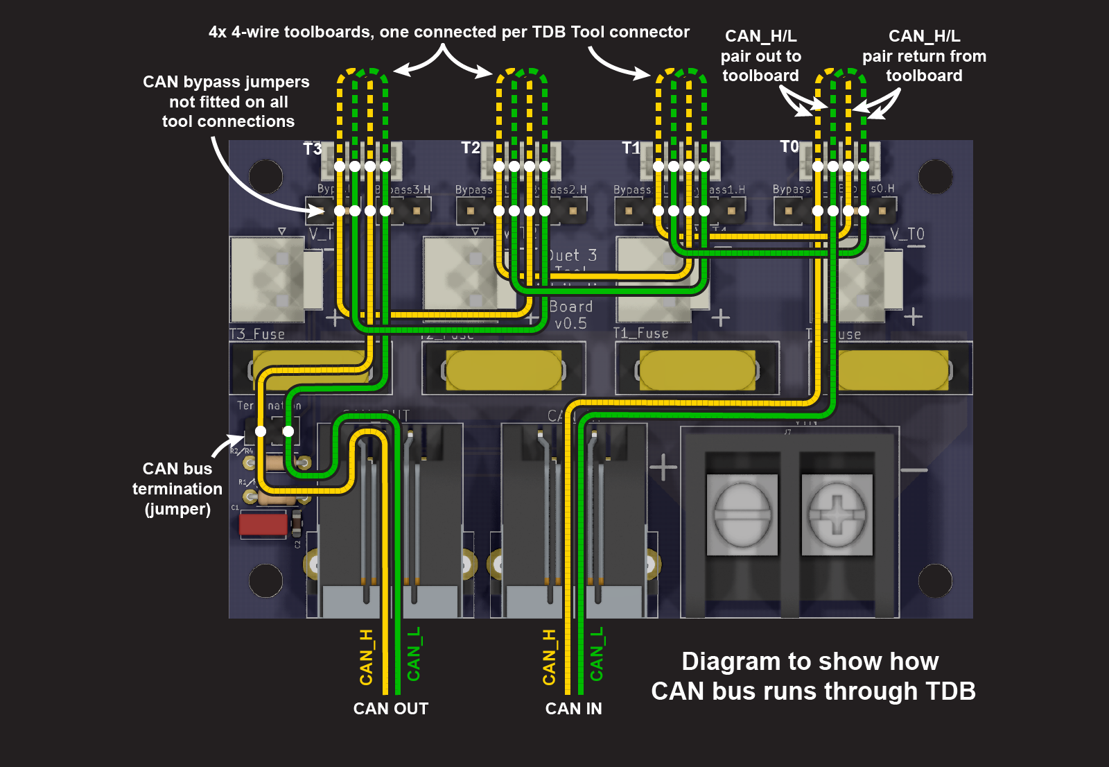
The Tool Distribution board isn't hard to understand; CAN1_H and CAN1_L connect to the TDB from CAN IN to, initially, Tool 0 connector. It goes out to a toolboard using the Tool 1 pins 3 and 4, and comes back in on pins 1 and 2. These are named CAN_H_0-1 and CAN_L_0-1, to show they connect from tool 0 to tool 1. This is done internally, to pins 4 and 3 of the Tool 1 connector. And so on, to Tool 2 and 3, and to CAN OUT. This keeps the CAN wires as a continuous bus, without the CAN_L or CAN_H wires crossing over, except at the ends of the bus, where it's terminated. You can see this in the wiring schematic: https://github.com/Duet3D/Duet3-Tool-Distribution-Board/blob/master/Tool Distribution v0.5/Duet3_Tool_Breakout_Schematic_v0.5.pdf
@j-pickens said in Duet 3 Mini 5+ with Canbus boards.:
I am currently wired Can H to Can H and Can L to Can L with a twisted pair between the CAN header on the Mini 5+ and the first Revo Roto Toolboard. The power to the Toolboard is on, the red activity light is blinking fast, not in sync withe the Mini 5+, and the termination jumper is installed on the Toolboard.
Try connecting the CAN wires the other way around. Probably easiest to switch them at the Mini 5+ end.
@j-pickens said in Duet 3 Mini 5+ with Canbus boards.:
There is nowhere on your search pages, even the Duet Reprapfirmware GCode dictionary to find these codes.
Again, thanks for your feedback. It is mentioned on every expansion board page, in the commissioning section, eg: https://docs.duet3d.com/Duet3D_hardware/Duet_3_family/Duet_3_Roto_Toolboard#commissioning
The wiki search function only finds exact matches to your search; we're limited by what the wiki software offers. Alternatively you can do a google search, but just search the wiki site. I'll add example usage of M122 to this section of the CAN page: https://docs.duet3d.com/en/User_manual/Machine_configuration/CAN_connection#using-can-addressesIan
-
@droftarts said in Duet 3 Mini 5+ with Canbus boards.:
Try connecting the CAN wires the other way around. Probably easiest to switch them at the Mini 5+ end.
Wow, really? Perhaps a wiring diagram for the whole setup? Am I asking too much?
I saw absolutely nothing in your documentation about wiring High to Low."The Tool Distribution board isn't hard to understand; CAN1_H and CAN1_L connect to the TDB from CAN IN to, initially, Tool 0 connector. It goes out to a toolboard using the Tool 1 pins 3 and 4, and comes back in on pins 1 and 2. These are named CAN_H_0-1 and CAN_L_0-1, to show they connect from tool 0 to tool 1. This is done internally, to pins 4 and 3 of the Tool 1 connector. And so on, to Tool 2 and 3, and to CAN OUT. This keeps the CAN wires as a continuous bus, without the CAN_L or CAN_H wires crossing over, except at the ends of the bus, where it's terminated. You can see this in the wiring schematic:"
If you can parse this into a functional wiring setup, that's great. I, however, cannot. My head is spinning.
Schematic of the wiring, please. I really don't think this is an unreasonable request. Look at what LGO and Bigtreetech are doing with their Type C connector toolboards. If you don't get your setup documented better, they will eat your lunch.
I talked to about 20 people at MRRF about Canbus, they all said it was a pain. Bill Steele, who is a very talented engineer said the only way he could get his working was with an oscilloscope. He told me not only was the i/o and address setup a problem, but that the boards he used had different i/o speeds, which he only detected with the oscilloscope. These were your boards.
-
I saw absolutely nothing in your documentation about wiring High to Low.
No, CAN_H goes to CAN_H, CAN_L to CAN_L. If you have just a Roto and Mini 5+, maybe you got them mixed up. It's easy enough to switch it over.
Perhaps a wiring diagram for the whole setup?
From https://docs.duet3d.com/Duet3D_hardware/Duet_3_family/Duet_3_Roto_Toolboard#can-connection
Schematic of the wiring, please.
Ian
Bed-slinger - Mini5+ WiFi/1LC | RRP Fisher v1 - D2 WiFi | Polargraph - D2 WiFi | TronXY X5S - 6HC/Roto | CNC router - 6HC | Tractus3D T1250 - D2 Eth
-
@droftarts I wired it as shown.
Here is a video:
https://youtu.be/Q99Rn5CfPhk -
@droftarts I found the problem, the Roto Toolboard connector was approx. 0.2mm out of the socket. You can see in the video how very slightly it was out. This killed the L connection, the H was still made. Perhaps a locking Molex plug like the other connectors on this board is called for. Hot glue for the win.
I am still requesting a wiring diagram of the main board/canbus expansion/and 1, 2, 3, or 4 tool board options, with wiring diagrams, bypass jumper, and terminator jumper setups for all 4 options. ANYBODY purchasing your boards who is not familiar with Canbus FD will need this documentation. Thanks.
-
@droftarts Here is a screengrab closeup of the disconnected canbus connector on the toolboard.
I measured it, it is 0.2mm out. Might need a better connector for this.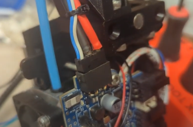
-
@j-pickens That looks like the wiring that came with the very early/prototype Roto boards. We now supply a cable with a moulded plug. I've used both the moulded plug version and the earlier 'open' cable with yellow and white wires, and haven't had any issue with those. Check you plug and socket on the Roto board for damage, debris, mis-aligned pins or crimps not fully engaged in the connector or cable.
I'll draw the Tool Distribution Board wiring today, but it doesn't need four different diagrams. The wiring and function of each Tool connector is the same:
- either the bypass jumpers are not fitted, and you have a tool board like the 1LC (with a 4-pin connector) with a pair of CAN wires going out from the connector, and a pair of CAN wires back to the connector
- or the bypass jumpers are fitted, and
- the Tool connector is either not used,
- or one or two stubs can be connected to either or both CAN_H/L pair.
Termination can either be done on the TDB with the jumper, or on the last toolboard in the CAN bus chain.
I talked to about 20 people at MRRF about Canbus, they all said it was a pain.
I've found the Duet implementation quite the opposite (the Klipper implementation is much more time consuming), so long as you're careful with the wiring.
It's a shame we can't do polls on the forumI've created a poll, as I'd like to see how many people thought it was difficult. Sure, for large systems with lots of boards there's a few hoops to jump through. But it's not like we reinvented the wheel. CAN and CAN-FD have wide usage across multiple industry sectors, and is a robust data transfer bus standard. I feel our documentation largely does a good job of covering it, and we're always improving it. For more advanced issues, there's this forum.Bill Steele, who is a very talented engineer said the only way he could get his working was with an oscilloscope. He told me not only was the i/o and address setup a problem, but that the boards he used had different i/o speeds, which he only detected with the oscilloscope. These were your boards.
Unless the boards are running wildly different firmware versions (and even then I'm not sure it would matter), I don't see how this could possibly be the case. The whole point is that they synchonise when connected. Sure, if you test each board in isolation, the onboard oscillator probably has some variance. But when connected to a mainboard, they sync, and the timing is inherited from the mainboard. Setting the address on boards is also clearly documented, eg https://docs.duet3d.com/Duet3D_hardware/Duet_3_family/Duet_3_Roto_Toolboard#set-the-can-address.
If they are running very different firmware, usually a 'factory reset' will get the board talking and flash compatible firmware. See https://docs.duet3d.com/en/User_manual/Machine_configuration/CAN_connection#factory-resetting-a-tool-or-expansion-board
Another possible issue is if you're powering the expansion board from a different PSU than the mainboard. This can cause a potential difference across the CAN bus, interfering with the signal. We recommend connecting the negative terminals of the power supplies together so they share a common ground, to negate this. See https://docs.duet3d.com/en/User_manual/Machine_configuration/CAN_connection#power-wiring
It is also possible to change the CAN frequency, with M952. How to do this is documented in the Gcode entry.
Ian
Bed-slinger - Mini5+ WiFi/1LC | RRP Fisher v1 - D2 WiFi | Polargraph - D2 WiFi | TronXY X5S - 6HC/Roto | CNC router - 6HC | Tractus3D T1250 - D2 Eth
-
@droftarts Thank you very much for this response. Looking forward to the wiring diagram.
-
@j-pickens I've done this today. Hopefully it shows how the CAN bus is routed through the board. I'll do diagrams for 2-wire connections tomorrow.
Ian
Bed-slinger - Mini5+ WiFi/1LC | RRP Fisher v1 - D2 WiFi | Polargraph - D2 WiFi | TronXY X5S - 6HC/Roto | CNC router - 6HC | Tractus3D T1250 - D2 Eth
-
@droftarts This is excellent. Of course, I need the 2 wire Can-FD, so tomorrow it is! I'll attempt a diagram tonight to see how close I get.
-
@droftarts How's your drawing coming? It looks to me like the only way to get the 2 wire signal from the T0 to T1 connector and so on is to use the bypass jumpers. To get T0 pins 1 and 2 to T1 pins 3 and 4. Or remove the jumpers? Not sure. I'll Ohm out these pins and see what is connected with the jumpers in and out.
-
@j-pickens said in Duet 3 Mini 5+ with Canbus boards.:
How's your drawing coming?
Slowly! I only want to do it once, so it necessitates a lot of checking. There's also quite a few variations. Here's what the 4-wire connection to a 1LC currently looks like:
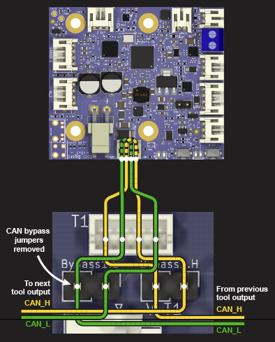
A 1LC can also be connected using 2-wire configuration. As a stub, without termination.
It looks to me like the only way to get the 2 wire signal from the T0 to T1 connector and so on is to use the bypass jumpers.
Correct. That's what I said earlier:
or the bypass jumpers are fitted, and
- the Tool connector is either not used,
- or one or two stubs can be connected to either or both CAN_H/L pair
By 'stubs' I mean a 2-wire connection to a toolboard.
Did you check your Tool Distribution board for solder bridges?
Ian
Bed-slinger - Mini5+ WiFi/1LC | RRP Fisher v1 - D2 WiFi | Polargraph - D2 WiFi | TronXY X5S - 6HC/Roto | CNC router - 6HC | Tractus3D T1250 - D2 Eth
-
@droftarts So, all bypass jumpers should be in place, and all toolboards should be wired to pins 3 and 4 on each T0-T3 connector. Pin 3 Low and Pin 4 High.
-
@j-pickens Yes. You can actually wire the toolboards to either pair of the tool connector, ie 1 and 2, or 3 and 4. Electrically it shouldn't matter which pair of pins you use. This also means you can wire two toolboards to each connector, one on each pair of the tool connector. I haven't actually been able to test this, but can't see any reason why it shouldn't, so it would be good to check it works. Make sure all 2-wire connections are each under 1m long.
Ian