Duet3D Logo Duet3D
    • Tags
    • Documentation
    • Order
    • Register
    • Login
    1. Home
    2. j.pickens
    • Profile
    • Following 0
    • Followers 0
    • Topics 7
    • Posts 27
    • Best 1
    • Controversial 0
    • Groups 0

    j.pickens

    @j.pickens

    1
    Reputation
    3
    Profile views
    27
    Posts
    0
    Followers
    0
    Following
    Joined Last Online

    j.pickens Unfollow Follow

    Best posts made by j.pickens

    • RE: Rounded Corners config.g acceleration parameters

      @bubblevisor I'm sure you are correct about the 6mm belts. The CoreXY design can minimize the effect to some extent due to the pulling from both directions in the design.

      However, what I was hoping to achieve was to correct the cornering problem as much as possible with the config file settings.

      With the help of @Phaedrux, I am very happy with the results!

      posted in Tuning and tweaking
      j.pickensundefined
      j.pickens

    Latest posts made by j.pickens

    • RE: Duet 3 Mini 5+ with Canbus boards.

      @droftarts So, all bypass jumpers should be in place, and all toolboards should be wired to pins 3 and 4 on each T0-T3 connector. Pin 3 Low and Pin 4 High.

      posted in Duet Hardware and wiring
      j.pickensundefined
      j.pickens
    • RE: Duet 3 Mini 5+ with Canbus boards.

      @droftarts How's your drawing coming? It looks to me like the only way to get the 2 wire signal from the T0 to T1 connector and so on is to use the bypass jumpers. To get T0 pins 1 and 2 to T1 pins 3 and 4. Or remove the jumpers? Not sure. I'll Ohm out these pins and see what is connected with the jumpers in and out.

      posted in Duet Hardware and wiring
      j.pickensundefined
      j.pickens
    • RE: Duet 3 Mini 5+ with Canbus boards.

      @droftarts This is excellent. Of course, I need the 2 wire Can-FD, so tomorrow it is! I'll attempt a diagram tonight to see how close I get.

      posted in Duet Hardware and wiring
      j.pickensundefined
      j.pickens
    • RE: Duet 3 Mini 5+ with Canbus boards.

      @droftarts Thank you very much for this response. Looking forward to the wiring diagram.

      posted in Duet Hardware and wiring
      j.pickensundefined
      j.pickens
    • RE: Duet 3 Mini 5+ with Canbus boards.

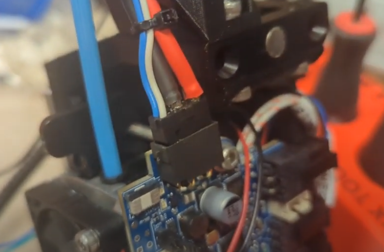
      @droftarts Here is a screengrab closeup of the disconnected canbus connector on the toolboard.
      I measured it, it is 0.2mm out. Might need a better connector for this.

      Screenshot from 2024-06-25 22-30-48.png

      posted in Duet Hardware and wiring
      j.pickensundefined
      j.pickens
    • RE: Duet 3 Mini 5+ with Canbus boards.

      @droftarts I found the problem, the Roto Toolboard connector was approx. 0.2mm out of the socket. You can see in the video how very slightly it was out. This killed the L connection, the H was still made. Perhaps a locking Molex plug like the other connectors on this board is called for. Hot glue for the win.

      I am still requesting a wiring diagram of the main board/canbus expansion/and 1, 2, 3, or 4 tool board options, with wiring diagrams, bypass jumper, and terminator jumper setups for all 4 options. ANYBODY purchasing your boards who is not familiar with Canbus FD will need this documentation. Thanks.

      posted in Duet Hardware and wiring
      j.pickensundefined
      j.pickens
    • RE: Duet 3 Mini 5+ with Canbus boards.

      @droftarts I wired it as shown.
      Here is a video:
      https://youtu.be/Q99Rn5CfPhk

      posted in Duet Hardware and wiring
      j.pickensundefined
      j.pickens
    • RE: Duet 3 Mini 5+ with Canbus boards.

      @droftarts said in Duet 3 Mini 5+ with Canbus boards.:

      Try connecting the CAN wires the other way around. Probably easiest to switch them at the Mini 5+ end.

      Wow, really? Perhaps a wiring diagram for the whole setup? Am I asking too much?
      I saw absolutely nothing in your documentation about wiring High to Low.

      "The Tool Distribution board isn't hard to understand; CAN1_H and CAN1_L connect to the TDB from CAN IN to, initially, Tool 0 connector. It goes out to a toolboard using the Tool 1 pins 3 and 4, and comes back in on pins 1 and 2. These are named CAN_H_0-1 and CAN_L_0-1, to show they connect from tool 0 to tool 1. This is done internally, to pins 4 and 3 of the Tool 1 connector. And so on, to Tool 2 and 3, and to CAN OUT. This keeps the CAN wires as a continuous bus, without the CAN_L or CAN_H wires crossing over, except at the ends of the bus, where it's terminated. You can see this in the wiring schematic:"

      If you can parse this into a functional wiring setup, that's great. I, however, cannot. My head is spinning.

      Schematic of the wiring, please. I really don't think this is an unreasonable request. Look at what LGO and Bigtreetech are doing with their Type C connector toolboards. If you don't get your setup documented better, they will eat your lunch.

      I talked to about 20 people at MRRF about Canbus, they all said it was a pain. Bill Steele, who is a very talented engineer said the only way he could get his working was with an oscilloscope. He told me not only was the i/o and address setup a problem, but that the boards he used had different i/o speeds, which he only detected with the oscilloscope. These were your boards.
      posted in Duet Hardware and wiring
      j.pickensundefined
      j.pickens
    • RE: Duet 3 Mini 5+ with Canbus boards.

      @dc42 Here is the response from: M122 B121
      CAN response timeout: board 121, req type 6024, RID 22

      I am currently wired Can H to Can H and Can L to Can L with a twisted pair between the CAN header on the Mini 5+ and the first Revo Roto Toolboard. The power to the Toolboard is on, the red activity light is blinking fast, not in sync withe the Mini 5+, and the termination jumper is installed on the Toolboard.

      posted in Duet Hardware and wiring
      j.pickensundefined
      j.pickens
    • RE: Duet 3 Mini 5+ with Canbus boards.

      @dc42 You see, here is a big problem with Duet and Canbus.
      You just told me to use M122 B121 to get a full Canbus report.
      There is nowhere on your search pages, even the Duet Reprapfirmware GCode dictionary to find these codes.
      If I hit the search bar while in the dictionary, and I search "Can" "Can-FD" or "Canbus" I get only 2 links to the Gcode dictionary. Now since you told me to use M122, I can search for it. But not knowing the Canbus codes, how am I supposed to find them?

      The two hits come up as M952 and M953. There appears to be no guide to Canbus here with a technical outline of how to set up and program these boards. Your documentation says things like:

      "Typically, the CAN bus is wired in a daisy-chain-style between boards. At one end will be the mainboard, with the CAN bus connecting to each subseqent board."

      Nothing specific for your products with pinouts and wiring diagrams for the Main Board/Distribution Board/Multiple Tool Boards. I still have absolutely no idea how to wire your distribution board based upon the cryptic pin labels in your diagram up top of my post, which termination jumpers are needed, and which bypass jumpers to use.

      This is getting very frustrating.

      posted in Duet Hardware and wiring
      j.pickensundefined
      j.pickens