G31 X Y significance
-
hey,
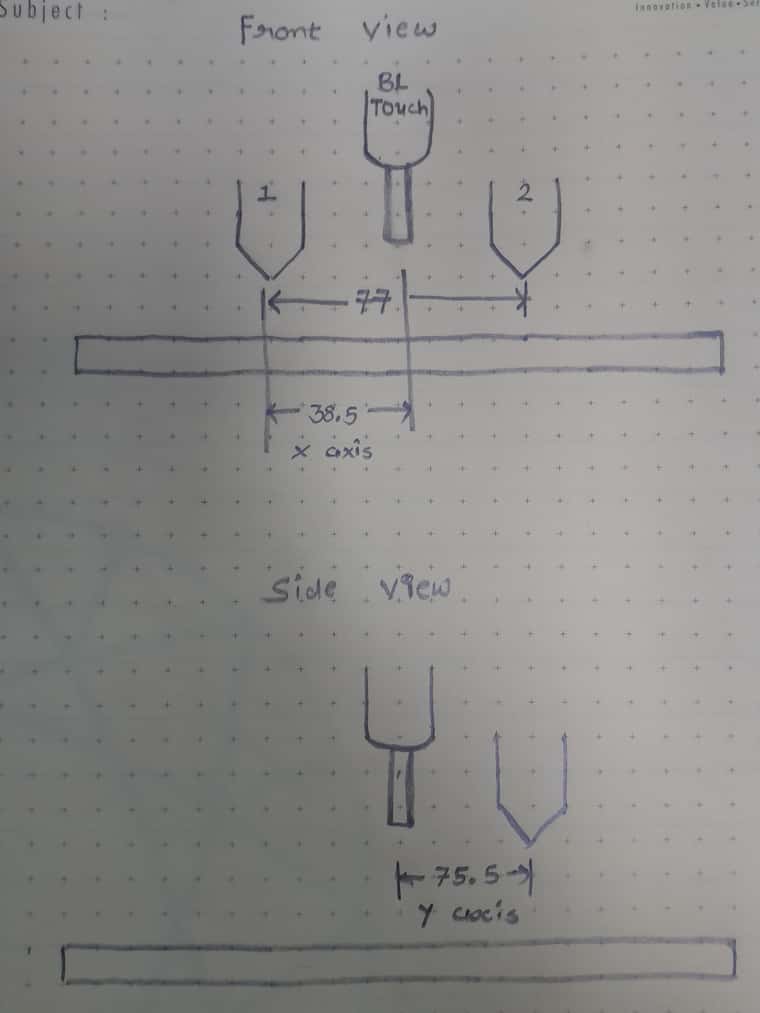
I have one machine with Duet3 MB6HC Dual Extruder. I want to understand declaration of Zprobe (BLtouch) & offsets to declare.I have declared extruder & z probe like below. Refer image to understand distances & 2 nozzle.

Also what's the significance of X & Y offset in G31. What does that mean in the software ? Where is offset is used by the software?
-
@R006 the X and Y offset is "how far does the nozzle need to move to be where the probe is". This is needed so when a bed mesh is constructed, a) the machine stays within the axis bounds and b) the generated mesh applies to where the nozzle is during print.
-
@oliof in your example, nozzle 1 is 38.5mm to the left of the probe, and nozzle 2 is 38.5mm to the right of the probe.
Let's stick with nozzle 1 for now. Assuming you have a 200x200 reachable area by the nozzle 1, if nozzle 1 is at position 0, the probe is at position 38.5. Assuming no ability to travel further to the right, this means the probe cannot be used to measure the bed on X coordinates < 38.5 since the print head physically cannot move there.
Assume the machine is commanded to probe six points
X38.5:Y0, X100:Y0, X200:Y0
X38.5:Y100, X100:Y100, X200:Y100
X38.5:Y200, X100:Y200, X200:Y200three of those won't be probed due to Y offset of the probe and RRF will skip them. Which will it be?
Usually, the nozzle offset is to the head reference point, which is the tip of the nozzle of the first tool. Other tools are offset using G10.
-
Since your side view of the setup does not indicate where the 0 point of the Y axis is, it's not possible to say for sure. Assuming the probe sits behind the nozzle to allow for a free view of the nozzles during print, it'd be a positive offset of 75.5 and the Y200 points wouldn't be reachable.
The offset is also used to make sure the measured mesh is properly applied to where the nozzle is during print. If the point X100:Y100 is measured, nozzle 1 actually is at x 100-38.5=61.5 and Y 100-75.5=24.5
Since we know the offset, the mesh is properly applied during printing with the nozzle at 100:100, and not where it was when the point was probed.
Now, pesky nozzle 2 ...
-
Nozzle 2 is offset 77mm to nozzle 1. When we enable nozzle 2 by whatever mechanism, we need to apply those 77mm nozzle offset to the main reference point, which we've established as the tip of nozzle 1.
Since we know the offset from probe to head reference point, and we know the offset from main reference point to nozzle 2, rrf applies the offset on top of the offset.
Now, what happens when you switch to nozzle 2 and send it to X position 200?
It ends up within the printable area, at 200 for nozzle 2. Nozzle 1 would be at 200-77=123, and the probe would be at X=161.5.
In RRF you define the nozzles as different tools with the XY offset for tool0 being 0,0, and every other tool offset relative to that using G10. When you switch the tools and recall the position of the previous tool (
G0 R2 X0 Y0 Z0), the G10 offset is applied, so nozzle 2 will end up where nozzle 1 was. For practical reasons, in the tool change macros we want to end up a bit above the print, so something likeG0 R2 X0 Y0 Z2followed byG0 R2 X0 Y0 Z0is often seen in tool change macros. -
Further documentation:
https://docs.duet3d.com/en/User_manual/Tuning/Defining_tool_and_Z_probe_offsets
https://docs.duet3d.com/User_manual/Reference/Gcodes#g0-rapid-move
https://docs.duet3d.com/User_manual/Reference/Gcodes#g31-set-or-report-current-probe-status
https://docs.duet3d.com/User_manual/Reference/Gcodes#g60-save-current-position-to-slot
https://docs.duet3d.com/User_manual/Reference/Gcodes#m557-set-z-probe-point-or-define-probing-grid