Adjusting the Nozzle height
-
@Chrashem After doing the G32, the Z home height is adjusted to fit the plane generated by the G32. In your case, it's moving the Z height down 0.16mm. I'd guess that if you did a bed mesh, it would show a saddle shape to your bed, but it's probably caused by a twist in the X axis rail, rather than a bent bed.
Do a bed mesh, and lets see what that looks like.
Ian
Bed-slinger - Mini5+ WiFi/1LC | RRP Fisher v1 - D2 WiFi | Polargraph - D2 WiFi | TronXY X5S - 6HC/Roto | CNC router - 6HC | Tractus3D T1250 - D2 Eth
-
I did the bed mesh, and unfortunately I think you're right. I guess my x-Axis Rail is bent in reason of the crash due to the firmware error.
This would be really sad, because this rail was really expensive (because its a milled out lightweight rail).But I also think I have some skew, if you look at the right side (rear).
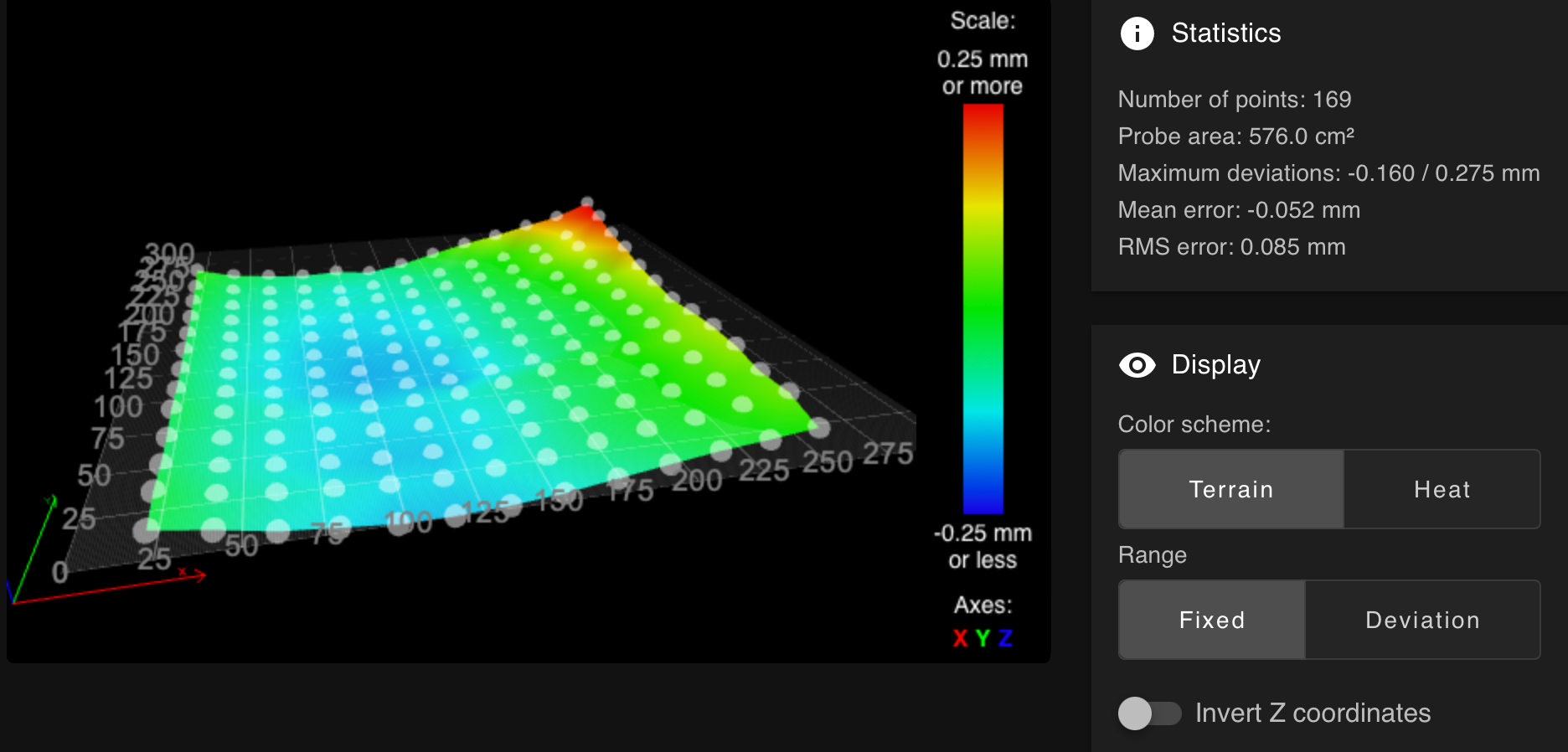
Here is the table of the bed mesh
RepRapFirmware height map file v2 generated at 2024-08-28 15:44, min error -0.160, max error 0.275, mean -0.052, deviation 0.085 axis0,axis1,min0,max0,min1,max1,radius,spacing0,spacing1,num0,num1 X,Y,20.00,260.00,20.00,260.00,-1.00,20.00,20.00,13,13 -0.036, -0.069, -0.110, -0.130, -0.150, -0.150, -0.140, -0.120, -0.089, -0.059, -0.030, -0.010, 0.015 -0.025, -0.074, -0.100, -0.115, -0.130, -0.135, -0.120, -0.100, -0.059, -0.030, -0.010, 0.025, 0.061 -0.044, -0.089, -0.115, -0.135, -0.145, -0.145, -0.130, -0.100, -0.054, -0.020, 0.005, 0.031, 0.056 -0.049, -0.089, -0.115, -0.130, -0.135, -0.135, -0.125, -0.105, -0.059, -0.030, 0.000, 0.041, 0.086 -0.035, -0.084, -0.105, -0.125, -0.135, -0.130, -0.115, -0.089, -0.049, -0.015, 0.015, 0.056, 0.095 -0.049, -0.094, -0.125, -0.145, -0.155, -0.150, -0.155, -0.125, -0.094, -0.039, -0.010, 0.036, 0.090 -0.049, -0.105, -0.130, -0.145, -0.160, -0.155, -0.145, -0.125, -0.079, -0.044, -0.015, 0.025, 0.076 -0.044, -0.100, -0.125, -0.145, -0.150, -0.150, -0.135, -0.105, -0.069, -0.049, -0.015, 0.036, 0.100 -0.044, -0.094, -0.115, -0.135, -0.140, -0.135, -0.125, -0.105, -0.064, -0.035, 0.010, 0.056, 0.120 -0.039, -0.084, -0.110, -0.125, -0.130, -0.130, -0.120, -0.094, -0.049, -0.015, 0.015, 0.071, 0.166 -0.025, -0.078, -0.094, -0.110, -0.110, -0.105, -0.094, -0.064, -0.030, 0.005, 0.056, 0.120, 0.191 -0.015, -0.059, -0.084, -0.094, -0.115, -0.100, -0.084, -0.054, -0.015, 0.015, 0.051, 0.125, 0.240 0.015, -0.035, -0.054, -0.069, -0.059, -0.079, -0.044, 0.010, 0.061, 0.100, 0.150, 0.196, 0.275 -
@Chrashem Where is the linear rail on the gantry? If it's on the front, it could be this has been displaced upwards in the middle by 0.16mm. You could try slackening off the bolts and realigning. To check if the gantry has been twisted, remove it and put it on a very flat surface, and see if you can see the twist; you may then be able to gently lever/twist it back.
Also looks like your tramming on the Y axis is a bit off, with the back right being high in the mesh, so linear rail is a bit low back there.
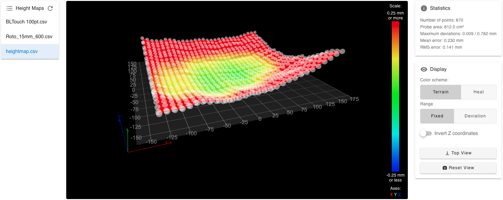
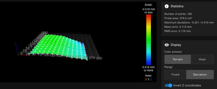
Otherwise, I wish my beds were as flat as that! This is my TronXY X5S, bed mesh from Scanning Z Probe
It will get a new bed, eventually!
Ian
Bed-slinger - Mini5+ WiFi/1LC | RRP Fisher v1 - D2 WiFi | Polargraph - D2 WiFi | TronXY X5S - 6HC/Roto | CNC router - 6HC | Tractus3D T1250 - D2 Eth
-
@droftarts said in Adjusting the Nozzle height:
Where is the linear rail on the gantry? If it's on the front, it could be this has been displaced upwards in the middle by 0.16mm. You could try slackening off the bolts and realigning. To check if the gantry has been twisted, remove it and put it on a very flat surface, and see if you can see the twist; you may then be able to gently lever/twist it back.
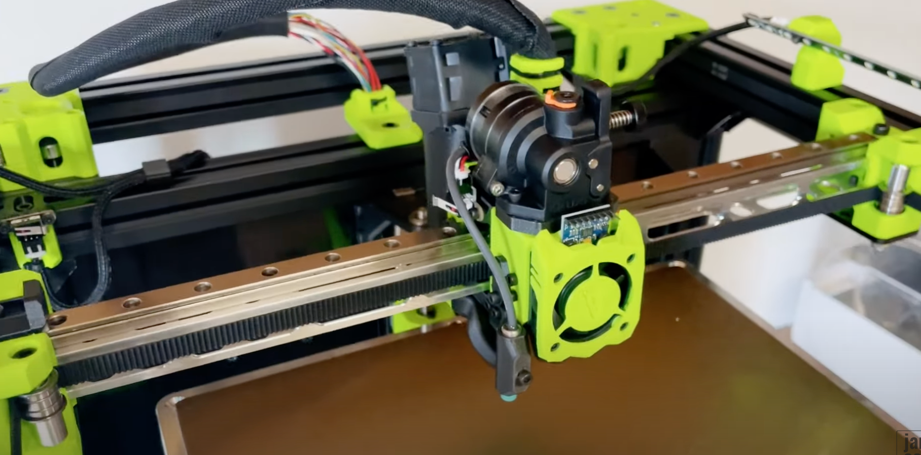
The linear rail is on the top of the gantry. Here you can see an example which I took from a video on YouTube:
Also looks like your tramming on the Y axis is a bit off, with the back right being high in the mesh, so linear rail is a bit low back there.
What would do you do? Loosen the Bolts in the right back and try to "adjust" the back the y Axis by slightly knocking with a hammer?
Otherwise, I wish my beds were as flat as that! This is my TronXY X5S, bed mesh from Scanning Z Probe
Oh hell, I thought my deviation is way too high. Before the crash it was less than 0.1mm over all. And I thought this was high :). But now I have the hope that I don't have to buy a new gantry.
But in general my head won't stop thinking and I ask myself what's THE or the best way for dealing with the z-offset?
Is it:
In general to get a basement:
*heating up to the print temperatures
*levelled bed (some laps of bed levelling)
*M561 to clear any transformation
*calibration of the nozzle clearance and the trigger height with adjusting it in the config.gBefore a print:
*homing the z-axis
*some laps of bed levelling until the adjustment is low enough (normally around 2-3 laps)
*run a mesh compensation of the print area
*printing?Is this okay or are there some stupid mistakes?
-
@Chrashem said in Adjusting the Nozzle height:
@droftarts said in Adjusting the Nozzle height:
Also looks like your tramming on the Y axis is a bit off, with the back right being high in the mesh, so linear rail is a bit low back there.
What would do you do? Loosen the Bolts in the right back and try to "adjust" the back the y Axis by slightly knocking with a hammer?
Something like that. It only needs to go up by 0.25mm. I'd loosen all the bolts along the rail (so it can straighten up) except the last one, loosen that one so it still holds the rail in position, and give it the lightest of taps to move it. If you can use some digital calipers to measure the position before and after, that may help. Then check by tramming (levelling) the bed, then bed mesh to see if the left and right sides of the bed are running parallel.
But in general my head won't stop thinking and I ask myself what's THE or the best way for dealing with the z-offset?
Is it:In general to get a basement:
*heating up to the print temperatures
*levelled bed (some laps of bed levelling)
*M561 to clear any transformation
*calibration of the nozzle clearance and the trigger height with adjusting it in the config.gBefore a print:
*homing the z-axis
*some laps of bed levelling until the adjustment is low enough (normally around 2-3 laps)
*run a mesh compensation of the print area
*printing?Is this okay or are there some stupid mistakes?
Clear any transformation with M561 before doing the bed levelling. You don't want an active bed mesh when doing bed levelling. Don't home Z between doing 'laps of bed levelling'. This should give you the bed as a flat plane. If you're not going to do a bed mesh, home Z. If you are, home Z, do the bed mesh, then home Z again. By homing Z at the end, it will shift any transformation using the Z=0 datum as it's reference. This should help consistency. For example, here's my bed.g and mesh.g:
; bed.g

M561                       ; clear any bed transform
G29 S2                     ; disable compensation
M671 X-181.5:181.5 Y0:0 S5 ; leadscrews at left (-181.5,0) and right (181.5,0)
G30 P0 X-85 Y0 Z-99999     ; probe near an adjusting screw
G30 P1 X85 Y0 Z-99999 S2   ; probe near an adjusting screw and report adjustments needed
G1 X0 Y0 F6000
I usually only need to run this twice. M561 is effectively the same as G29 S2 in this case, though I like having both of them in.
; mesh.g

M561   ; clear any bed transform
G29 S2 ; disable compensation
G28 Z  ; home Z
G29 S0 ; probe the bed and enable compensation
G28 Z  ; home Z
Hope that helps.
Ian
Bed-slinger - Mini5+ WiFi/1LC | RRP Fisher v1 - D2 WiFi | Polargraph - D2 WiFi | TronXY X5S - 6HC/Roto | CNC router - 6HC | Tractus3D T1250 - D2 Eth
-
This helps a lot! Thank you!
On Saturday I will mount a dial gauge with a magnetic base on the printer and try to adjust the back of the y axis.Regarding the levelling/bed mesh: If I understood your advices in the right way the process should be:
1 Turning the printer on
- heat it up
- homing all axis (after a start of the printer, otherwise it couldn't move (except commands with disabled axis limits))
2 creating a flat plane
-
M561 (Clear all mesh compensation)
*1-2 laps of bed levelling -
2.1 If I do a bed mesh:
- Homing z
- G29 S2 (disabling the compensation )
- do the bed mesh
-
homing z again
-
2.2 With no bed mesh
- Just homing z
-
3 print and having fun!
Is this correct?
The M557 for defining the mesh grid is in your config.g?
-
@Chrashem said in Adjusting the Nozzle height:
Is this correct?
Well, it's the way I do it, and I get good consistency this way.
The M557 for defining the mesh grid is in your config.g?
Yes.
Ian
Bed-slinger - Mini5+ WiFi/1LC | RRP Fisher v1 - D2 WiFi | Polargraph - D2 WiFi | TronXY X5S - 6HC/Roto | CNC router - 6HC | Tractus3D T1250 - D2 Eth
-
Thank you! I will try it!
-
@droftarts
Hi Ian, maybe I'm stupid, but are you sure that I have to lift the rail?Also looks like your tramming on the Y axis is a bit off, with the back right being high in the mesh, so linear rail is a bit low back there.
I thought a bit about it, and in reason to the point that my printer is a core XY which means, that the z- axis is working to the opposite direction (pointing downwards) , I guess I have to lower the rail.
I assume I have to think inverse.
For Example: If I want to have a z movement of z= 20 mm the printer would lower the bed, because the printhead can't move in z direction.So with this in mind I would assume, that a positiv z- value in the height map means that the point is more away from the nozzle.
If this theory is correct, I have to lower the y axis on the right side.I hope you understand what I mean.
kind regards
Dennis -
@Chrashem Positive Z movement always moves the bed and print head farther apart, regardless if that is up or down.
-
maybe we have a little misunderstanding. You're 100 % right but here in this case @droftarts gave me a hint regarding the gantry adjustment based on the height map. My question is, if I have to interpret the result of the height map in the opposite direction.
In the heightmap the positive z- axis is pointing upwards, but in reality a high z-value means that my bed is moving downwards.
And in the Duet Web Control you have this "invert z coordinates". In wich case I have to use it?
Here without the slider:
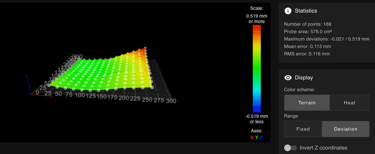
Here with the slider:
I would assume, that in my case I have to invert the coordinates.
-
@Chrashem it’s a good point, and I’m not exactly sure which way the mesh values work! If you hover the mouse pointer over the back right point, it will give you the XYZ coordinates. I have always taken this as the height measured by the probe at that point. Ie the bed is 0.275mm high in that back corner. Because we know that the bed is flat, it’s that the nozzle is low, and should be moved up, by moving the gantry up. Due to the shape, it looks like the rail needs to go up.
If the points shown are actually the correction applied, then yes, it works the other way. But I’m pretty sure that’s not what the mesh shows. I’ve used the mesh for tramming before, and never noticed my adjustment going the wrong way.
Ian
Bed-slinger - Mini5+ WiFi/1LC | RRP Fisher v1 - D2 WiFi | Polargraph - D2 WiFi | TronXY X5S - 6HC/Roto | CNC router - 6HC | Tractus3D T1250 - D2 Eth
-
I want to give you a feedback: I was wrong! I had to lower the y axis. I adjusted it and now my maximum deviation is about 0.2 mm. I feel good with it!
I printed some califlowers and could fine-tune the Skew with a M556.
I think my machine back in business!
Thx for your help!