Input shaping on large mass print head
-
@BartW22 can you post your config? Looks like very low jerk settings
Owns various duet boards and is the main wiki maintainer for the Teamgloomy LPC/STM32 port of RRF. Assume I'm running whatever the latest beta/stable build is
-
@jay_s_uk I'm unable to get them now. But I'll try to do it tomorrow first thing in the morning!
Edit: But yes, the printer uses very low jerk settings. From the top of my head it uses 40mm/min. I have used higher values, but then it sounds like the steppermotors struggle too much. -
@jay_s_uk Good morning!
I was able to get the oscillations on camera way better: the video (watch out, there are some loud background noises!)
And my jerk (and additional) settings are as follows:M566 X20.00 Y20.00 Z12.00 E120.00 ; set maximum instantaneous speed changes (mm/min) (jerk) M203 X6000.00 Y6000.00 Z800.00 E10000.00 ; set maximum speeds (mm/min) M201 X100.00 Y100.00 Z20.00 E300.00 ; set accelerations (mm/s^2) M906 X1000 Y1000 Z1000 E1000 I30 ; set motor currents (mA) and motor idle factor in per centThe used steppermotors (two on both X and Y) are 23LC051-025-8W-F8-1.0. The pulley system is set up like this . I don't know if it matters, but I provided it just to be sure.
Thanks! -
@BartW22 it would be good to see the whole config so we can see how everything is setup.
Those jerk settings are really low though. With the speeds you'll be going and the very low changes in direction I don't think it will be possible to apply input shaping but I may be wrong -
@jay_s_uk I'm already working on increasing the jerk settings, thanks to your suggestion.
Here is the config file:; Configuration file for Duet WiFi (firmware version 2.03) ; executed by the firmware on start-up ; ; generated by RepRapFirmware Configuration Tool v3.3.15 on Wed Dec 14 2022 15:12:07 GMT+0100 (Midden-Europese standaardtijd) ; General preferences M575 P1 S1 B57600 ; enable support for PanelDue G90 ; send absolute coordinates... M83 ; ...but relative extruder moves M550 P"pastaprinter" ; set printer name M564 H0 ; Network M552 S1 ; enable network M586 P0 S1 ; enable HTTP M586 P1 S0 ; disable FTP M586 P2 S0 ; disable Telnet ; Drives M569 P0 S1 ; physical drive 0 goes forwards M569 P1 S0 ; physical drive 1 goes backwards M569 P2 S1 ; physical drive 2 goes forwards M569 P3 S0 ; physical drive 3 goes backwards M569 P4 S1 ; physical drive 4 goes forwards M569 P5 S0 R1 T3.4:3.4:6:0 ; physical drive 5 goes backwards M569 P6 S0 R1 T3.4:3.4:6:0 ; physical drive 6 goes backwards M584 X3:4 Y0:1 Z5 E6 ; set drive mapping M350 X16 Y16 Z16 E16 I1 ; configure microstepping with interpolation M92 X41.22 Y41.22 Z2560.60 E330.00 ; set steps per mm M566 X200.00 Y200.00 Z12.00 E120.00 ; set maximum instantaneous speed changes (mm/min) (jerk) M203 X6000.00 Y6000.00 Z800.00 E10000.00 ; set maximum speeds (mm/min) (stond op Z300) (20/11 -> M201 X100.00 Y100.00 Z20.00 E300.00 ; set accelerations (mm/s^2) M906 X1000 Y1000 Z1000 E1000 I30 ; set motor currents (mA) and motor idle factor in per cent M84 S30 ; Set idle timeout M915 P0:1:3:4 S3 R2 F0 H400 ; stall detection ; Axis Limits M208 X0 Y0 Z0 S1 ; set axis minima M208 X760 Y360 Z1000 S0 ; set axis maxima ; Endstops M574 X1 S1 P"xstop" ; set x-axis high endstop M574 Y1 S1 P"ystop" ; set y-axis high endstop M574 Z1 S1 P"zstop" ; set z-axis high endstop ; Z-Probe M558 P0 H5 F120 T6000 ; disable Z probe but set dive height, probe speed and travel speed M557 X15:215 Y15:195 S20 ; define mesh grid ; Heaters M140 H-1 ; disable heated bed (overrides default heater mapping) ;M305 P0 T100000 B4138 R4700 ; ??? ;M305 P1 T100000 B4138 R4700 ; ??? ; Sensors M308 S0 P"e1temp" Y"thermistor" T10000 A"T_E-motor" ; M955 P0 C"SPI.CS2+SPI.CS1" I50 ; versnellingsmeter LIS3DH M593 P"zvddd" F12 S0.05 ; Fans M950 F1 C"fan2" ; extruder motor fan M106 P1 S1 T45 H0 ; extruder motor fan on from 45C and above ; Tools M563 P0 S"pasta extruder" D0 F0 ; define tool 0 G10 P0 X0 Y0 Z0 ; set tool 0 axis offsets G10 P0 R0 S0 ; set initial tool 0 active and standby temperatures to 0C ; External stop and pause buttons M950 J1 C"e1stop" ; defines input (red button) of E1 stop as "tool 1" M581 P1 S1 T0 ; assigns tool 1 trigger to stop function M950 J2 C"e0stop" ; defines input (yellow button) of E0 stop as "tool 2" M581 P2 S1 T1 ; assigns tool 2 trigger to pause function ; Miscellaneous M575 P1 S1 B57600 ; enable support for PanelDue M501 ; load saved parameters from non-volatile memory T0 ; select first tool -
@BartW22 how do you have the 2 motors connected to X and 2 motors connected to Y? Are they both ran off the same driver?
Those stepper motors are also rated for 1.5A so you can increase the current supplied them to 1200 (1.2A) -
@jay_s_uk Each motor uses one driver on the Duet 2 Wifi. The X motors are driven by X_MOT and E1_MOT and the Y motors are driven by Y_MOT and E0_MOT.
Increasing the jerk did make the moves in corners a bit smoother, so the print head isn't shaking that much anymore.
Is it reasonable to increase the jerk so much that the print head will oscillate above 10Hz and thus can be compensated by Input Shaping> -
@BartW22 ah yes, i see on the motors now.
the rule of thumb for jerk is i try to aim for between 300 and 600 mm/min (5-10mm/s). that should bring you in to the right range for input shaping.
Ideally you should also try and determine what the maximum speeds are that your system can handle as those max speeds will be used by the input shaping plugin -
@BartW22 the minimum input shaping frequency supported on Duet 3 boards is 5.7Hz and on Diet 2 is it 7.15Hz. Is that low enough for you?
-
@jay_s_uk @dc42 I've upted the jerk settings to 900mm/min, which the printer is able to handle. I also started to play with the max speed which lies around 6000-8000mm/min.
With those settings I recorded motion profiles with no desirable result so far:
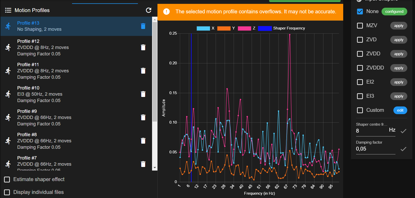
This is a profile without input shaping. The mounting orientation of the accelerometer is so that Z is recording the Y direction. X is for the X direction.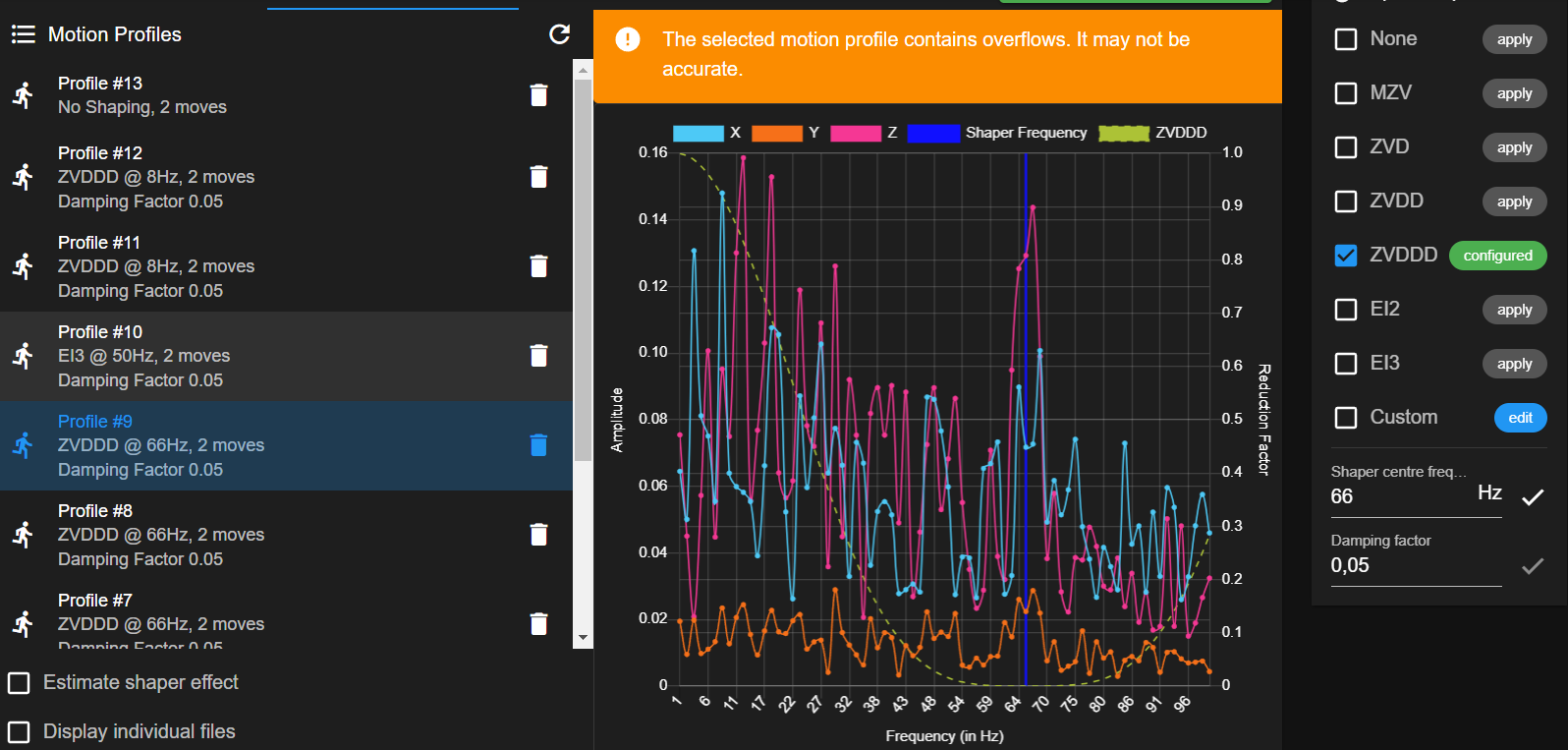
Here the ZVDDD input shaper is used at 66Hz. Although it looks like it reduces that frequency, that's not the frequency the print head is oscillating at. I presume it's the resonance frequency of the printer frame.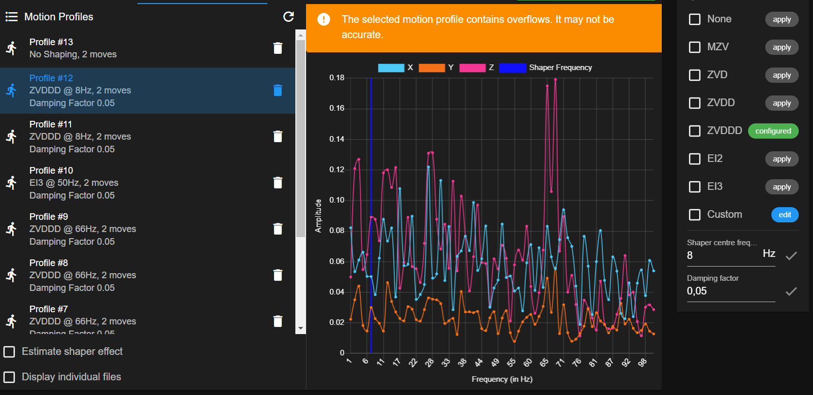
The ZVDDD input shaper at 8 Hz also doesn't seem to have any effect.What I'm struggling with is that the movements used to record a motion profile don't recreate the oscillations that occur while printing. I tried to add custom movements for recording, but the print head always comes to a full stop in between moves. Is there a way to record frequencies while printing or maybe write some gcode to recreate the occuring movements while recording?
Thanks! -
@BartW22 Having looked at your video those oscillations look to be at a much lower frequency than the limit mentioned above by DC42. they seem more 0.5Hz or possibly even lower. I'm not sure that the RRF accelerometer and IS plugin can really capture those sorts of motion. It's also worth noting that your captures seem to be indicating that an overflow occurred during the recording, which is probably not good.
There are various apps available for mobile phones (like the physics toolbox) that will capture acceleration and graph it. I wonder if using one of those might be a solution for measuring what is going on?
-
@gloomyandy I've attached my phone to the print head and got this result: 2024-10-1417.17.34.csv
I not sure how to read it (hopefully one of you can). Otherwise I have to graph it and see what comes from that.
Is this helpful? -
@BartW22 Hmm I've had a quick look, but unfortunately it looks like it was not using a fixed sample rate, that makes it a little tricky to process the results with the online tools I could find. But even if you can work out the frequency I really doubt if the RRF input shaper is going to be able to handle that level of oscilation it is a bit more than your typical 3d printer ringing! But what do I know, maybe it can help.
-
Feature request has been opened here:
https://github.com/Duet3D/InputShapingPlugin/issues/4
Will move it to RRF though as it will need changes to RRF before the plugin.
-
@BartW22 if your resonances are at low frequencies then you should reduce the sampling rate (M955 S parameter) to between 200Hz and 800Hz and increase the sample time e.g. to 4 seconds. Also un-check the box that causes samples to be taken throughout the move, because you will get more accurate low-frequency results if you sample only when the move has finished.
The minimum input shaping frequency currently supported is around 5.8Hz on Duet 3 boards and 6.2Hz on Duet 3. I can reduce it in 3.6 firmware, however a low input shaping frequency will lead to larger artefacts unless the print speed is also reduced.
-
@T3P3Tony I think it requires an enhancement to the input shaping plugin to configure the sample time.
