Can this 5-axis FDM be configured with RRF?
-
Posting here since it's 5 axis, but this is for a 3D printer project.
Only focusing on the rotational axes in this topic, I want to build the illustrated design so that the nozzle can rotate.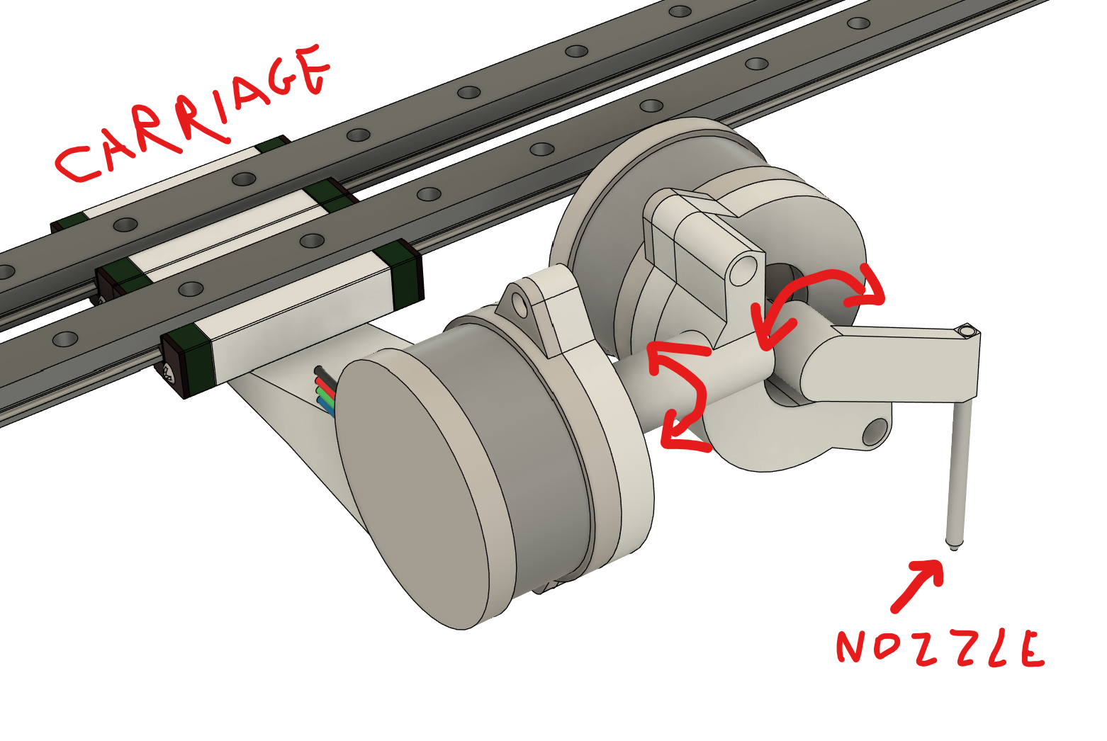
At rest position the axis closest to the end effector is parallel to the Y axis, and the next one is parallel to the X axis. Both have offsets (one relative to the other and to the end effector).
XY axes are CoreXY, Z connected to the carriage, fixed bed. So reading the documentation this would be a XYZAB or something like that? And there should be some way to configure them using M669, but am not sure the firmware has support for all the parameters. It mostly talks about AC/BC configurations where offsets are supported, but doesn't mention offsets for AB and I couldn't find a good example configuration to get inspiration from.What I would like to get from the firmware is the IK solving so that when the g-code asks for a motion that involves A and B axes rotation, it will adjust the XYZ position so that the end effector stays in the same place with relation to the bed, but changes angles.
I'm asking here if this is supported by the firmware so that I don't invest time in building a device that cannot be configured.
Edit: here are the two vectors I'm wondering how to configure.
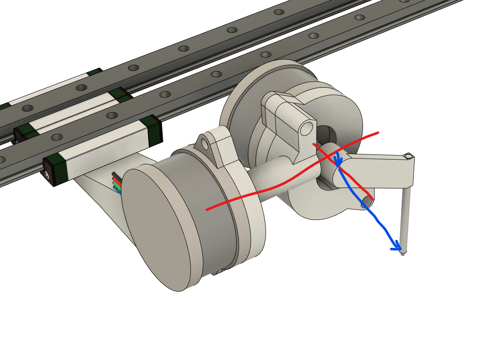
-
@MihaiDesigns I don't think that kinematic type is supported in the 'normal' firmware, but there is work on-going on a version of RRF that, I think, might support it, which is @JoergS5's work: https://docs.duet3d.com/en/User_manual/Machine_configuration/Configuring_RepRapFirmware_for_a_Robot_printer
The development discussion is here, though focus is more on palletised robots (4 axis arms, basically): https://forum.duet3d.com/topic/17421/robotic-kinematics/383
This recent thread describes a machine where moves in BC move XYZ too, I think similar to your requirement: https://forum.duet3d.com/topic/35865/voron5x-with-rtcp/Hope that helps!
Ian
Bed-slinger - Mini5+ WiFi/1LC | RRP Fisher v1 - D2 WiFi | Polargraph - D2 WiFi | TronXY X5S - 6HC/Roto | CNC router - 6HC | Tractus3D T1250 - D2 Eth
-
@droftarts said in Can this 5-axis FDM be configured with RRF?:
@MihaiDesigns I don't think that kinematic type is supported in the 'normal' firmware, but there is work on-going on a version of RRF that, I think, might support it, which is @JoergS5's work: https://docs.duet3d.com/en/User_manual/Machine_configuration/Configuring_RepRapFirmware_for_a_Robot_printer
The development discussion is here, though focus is more on palletised robots (4 axis arms, basically): https://forum.duet3d.com/topic/17421/robotic-kinematics/383
This recent thread describes a machine where moves in BC move XYZ too, I think similar to your requirement: https://forum.duet3d.com/topic/35865/voron5x-with-rtcp/Hope that helps!
Ian
I see that the robot printer still implements only AC and BC (used for the Voron5X).
Since I need this for a PoC, I guess one somewhat easy solution is to write a gcode processor that calculates the XYZ compensation when rotating A and B. I mean it would anyways be some generated gcode to print basic shapes with steep overhangs (it's one of the reasons I wanted the rotating axes).
In which case the firmware needs to move some extra axes I suppose, like G1 X Y Z U V? Then it would move all axes at the same time? And my gcode processor segments the moves into very short segments (0.2mm in length or so). Am I going the right direction here? -
@MihaiDesigns If you use a Gcode post process to calculate the offsets, then yes you can move multiple axes at the same time with the 'normal' firmware.
Ian
-
@MihaiDesigns Pre-processing such a big part of a sliced file will mess up the extrusion calculation, too.
Unless your slicer already knows about the extra axes and it's just RRF that needs to be altered. -
@MihaiDesigns this robot type is very similar to Gantry Robot (eg ABB IRB 6620LX), discussed in the book Pardos-Godor Screw Theory for Robotics. It is 6 axis. The book's approach finds all solutions by calculation (no iterations needed).
It can be described by the order of the axes (linear, then rotational etc) and the tool orientation and position.
The inverse calculation is described in the book, which divides the calculation into subproblems. You will have to handle multiple solutions for the inverse kinematics.
I tried different approaches, starting with Denavit-Hartenberg and Euler angles, but those calculations have many special cases like Gimbal lock and special handling when 90 degrees are crossed etc. This is "local calculation", meaning the axes are calculated one after another. The "global calculation" method by using screw theory is much better and avoids some of the special cases (the singularity situations).
I currently develop a general approach which will cover your case, but I don't want to make a promise about the time frame. Robot kinematics is planned for RRF 3.6.
An important aspect which I want to add is that those kinematics need to take into account the orientation of the tool, in addition to the position. Some RRF code expects the tool to be vertical, eg mesh compenstation (probably same with baby steps). It doesn't work with non-vertical tools. It is currently a workaround to include the tool into the calculation tool chain, so you have control over the calculation, and set the tool to 0 length.
Last comment: with two rotational axes you will not be able to make all rotational movements. 3 rotational axes would be better (like the Gantry robot I mentioned above). Easiest to calculate is if they are mechanical built as spherical, i. e. the three axes cross in one point. Similar to how most industrial robots are built with axes 4 to 6 in the head.
-
@JoergS5 said in Can this 5-axis FDM be configured with RRF?:
built as spherical, i. e. the three axes cross in one point.
Just out of curiosity:
This crossing point is necessarily the tip of the nozzle? Or nozzle + layerheight? -
@o_lampe no, it's the crossing point of the three last axes of the industrial robot. The calculation of the inverse kinematics is much easier when they cross. The nozzle will simply add with his length and orientation.