3 fans on tool board 1lc?
-
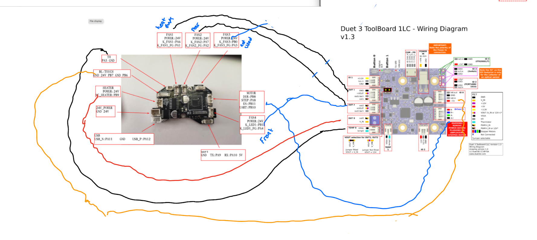
@jay_s_uk I think you might be right. Checking the wiring the two cooling fans are connected to FAN2 and FAN4 on the Sovol Board.
Which are in turn defined as generic fans fan0 and fan1 - in printer.cfg
[fan_generic fan0] # back model cooling fan
pin: extra_mcu:PA7
max_power: 1.0[fan_generic fan1] # front model cooling fan
pin: extra_mcu:PB1
max_power: 1.0From looking at the macro.cfg - it looks like fan0 and fan1 are switched on and off together - so will try wiring them both up to Out2 as you suggest
Next issue is the fans are probably 24v - so might have to change the fans?
[gcode_macro M106]
gcode:
{% set fan = 'fan' + (params.P|int if params.P is defined else 0)|string %}
{% set speed = (params.S|float / 255 if params.S is defined else 1.0) %}
{% if fan == 'fan3'%}
SET_FAN_SPEED FAN={fan} SPEED={speed}
{% else %}
SET_FAN_SPEED FAN={'fan0'} SPEED={speed}
SET_FAN_SPEED FAN={'fan1'} SPEED={speed}
{% endif %}[gcode_macro M107]
gcode:
{% set fan = 'fan' + (params.P|int if params.P is defined else 0)|string %}
{% if fan == 'fan3'%}
SET_FAN_SPEED FAN={fan} SPEED=0
{% else %}
SET_FAN_SPEED FAN={'fan0'} SPEED=0
SET_FAN_SPEED FAN={'fan1'} SPEED=0
{% endif %} -
@dwuk said in 3 fans on tool board 1lc?:
Next issue is the fans are probably 24v - so might have to change the fans?
What voltage are you supplying the toolboard?
-
@T3P3Tony I think I'm going to need 24v for the hot end - so 24v input I guess.
-
@T3P3Tony Ah - I see you can select the output voltage as being VIN (I didn't spot that initially) - so I think that way I will be able to get 24v on Out1 and Out2 - so that should solve my fan issue. thanks
-
@dwuk I just ended up getting blowers without tachs and wiring them up in parallel.
-
@gnydick Thanks - I think that is what I am going to do too. Or I might just only have one blower fan.
-
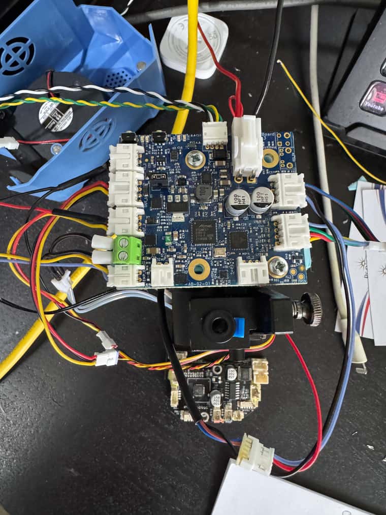
@dwuk Now wired up.
One of my blower fans is 2 wire and the other 3 - so I think that works quite well.
Only issue I had was finding gnd for out_2. Ended up taking it off of IO1.
-
@dwuk Update
First tried with 3 fans connected to +VOUT and GND on both Out1 and Out2.
- Fans were permanently on full speed.
Next tried with3 fans connected with out1/out2 and GND.
- None of the fans would work.
Finally found some more documentation that says you have to connect the red wires to +VOUT and Negative connections Out1 and Out2. - even though the diagram for the 1LC says that these are VIN or 12v+
- Tried that and it seemed to be working - but then I got burning smell from 2 pin fan (which was connected to the same Red and Black as the 3 pin fan).
Good news though is that the 3 pin Hotend and cooling fans both now work properly.
I think however that the 2 pin fan is fried - so will have to get another one and work out how to connect it. -
@dwuk Unless labelled otherwise (eg '5V PWM' for servos on the Mini 5+), all OUT and IO headers are switched on the Ground side, it's just how MOSFETs work. I tend to agree with you that the 'KEY' on the wiring diagram could be better labelled, and rather than "PWM V_IN" or "PWM V_FAN" it should perhaps be "PWM GND". I've made @T3P3Tony aware of this. As far as I can tell it's marked the same on every wiring diagram!
Are the fans running on 24V or 12V VIN, or 12V from the voltage regulator? There's a current limit if running from the 12V regulator, see https://docs.duet3d.com/Duet3D_hardware/Duet_3_family/Duet_3_Toolboard_1LC#operating-limits
800ma total (OUT_1 and OUT_2 pins only, when 12V selected)
If powered from VIN, there's a 2A current limit (what the pins and connectors can cope with), see https://docs.duet3d.com/Duet3D_hardware/Duet_3_family/Duet_3_Toolboard_1LC#description-of-connections
OUT_1 : 4-wire fan output (also accepts a 2- or 3-wire fan) intended for use as the print cooling fan. 2A total max current for OUT1 and OUT2 when VIN selected (v1.1 board), 0.8A total max current for OUT1 and OUT2 on 12V.
Some blower fans might be drawing too much current, and kill the MOSFET.
Ian
Bed-slinger - Mini5+ WiFi/1LC | RRP Fisher v1 - D2 WiFi | Polargraph - D2 WiFi | TronXY X5S - 6HC/Roto | CNC router - 6HC | Tractus3D T1250 - D2 Eth
-
All the fans I am running are 24v.
The 2 pin one I think fried say 0.5a on it - I connected to Out2 on the black wire and +Vout on the red wire (in parallel to a 3 pin fan on the same two wires (plus also out2.tach).I still have another one of these two pin fans on the other print head that is still connected to the Klipper board at the moment - so will check what voltages are going to that.
Will try running the fans individually connected next to see if it is just both fans being on the same output that is causing them to break.