Sovol SV08 Multiple Motion System Upgrade.
-
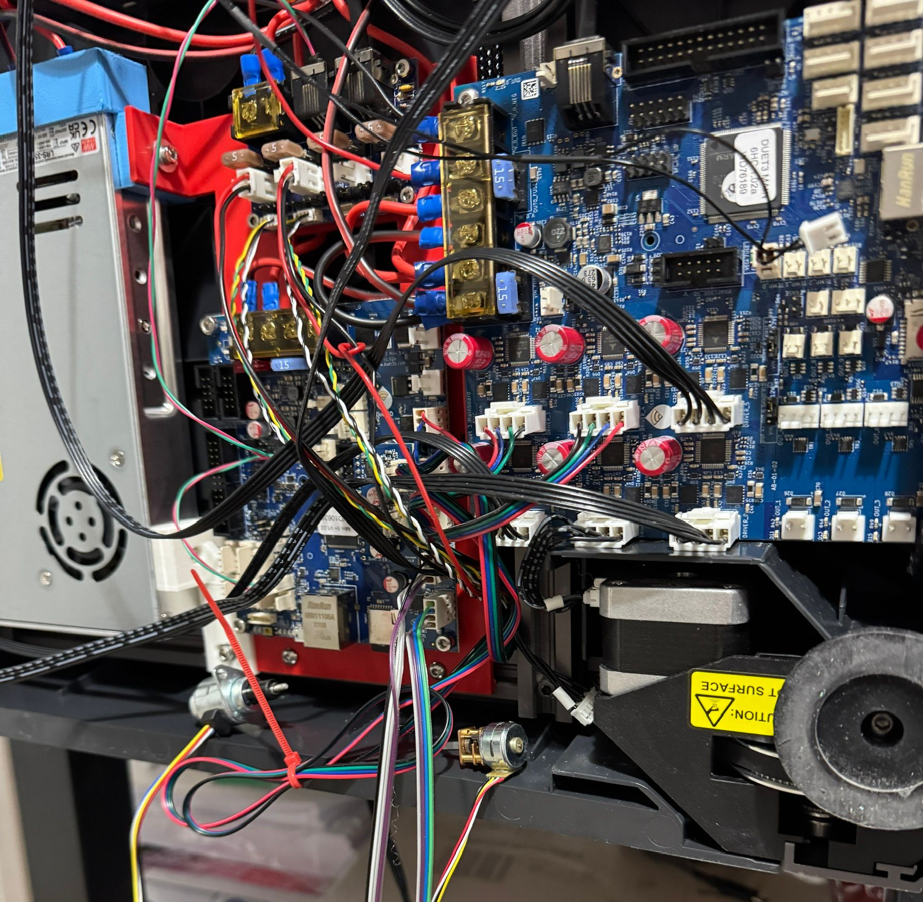
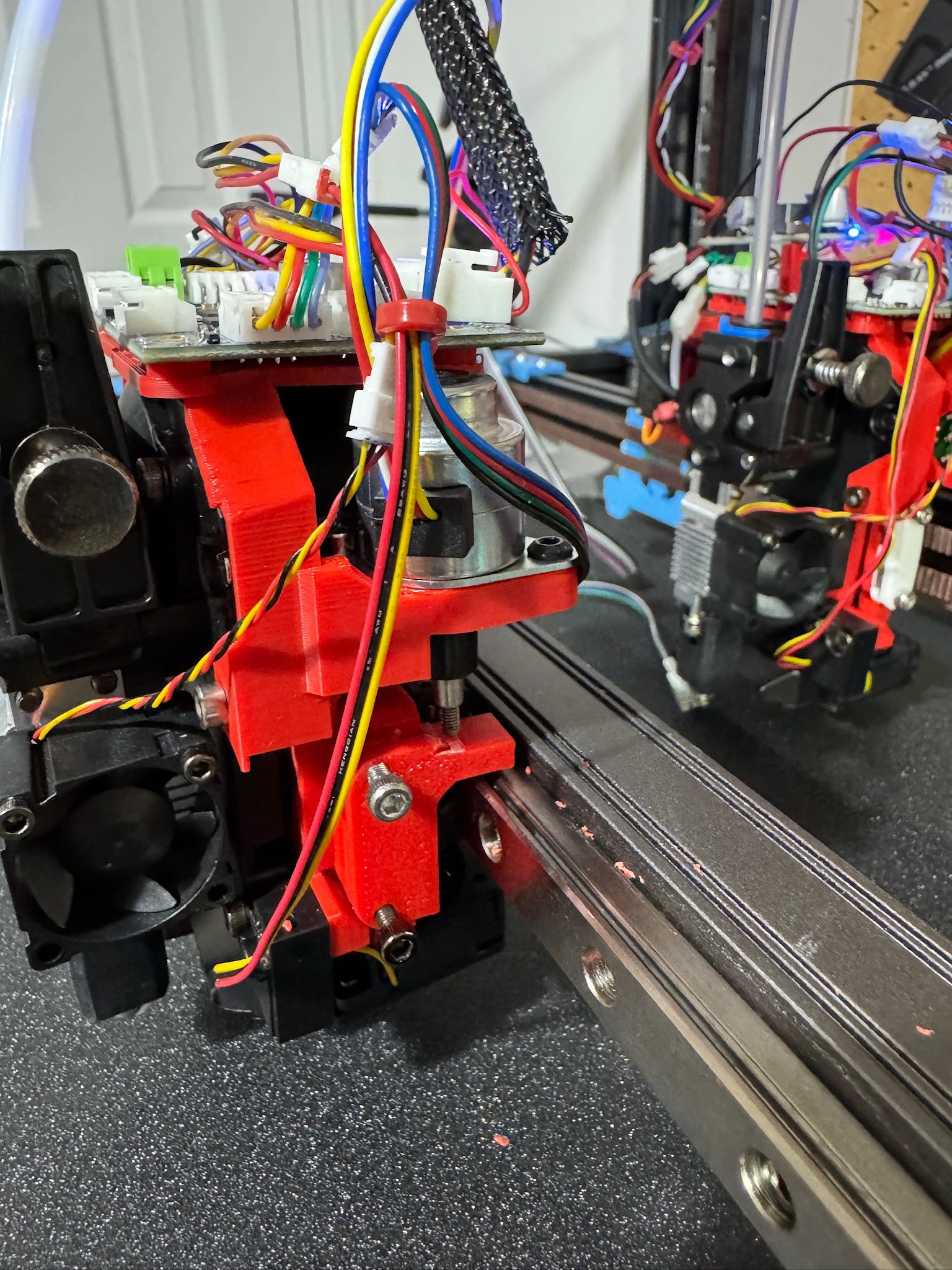
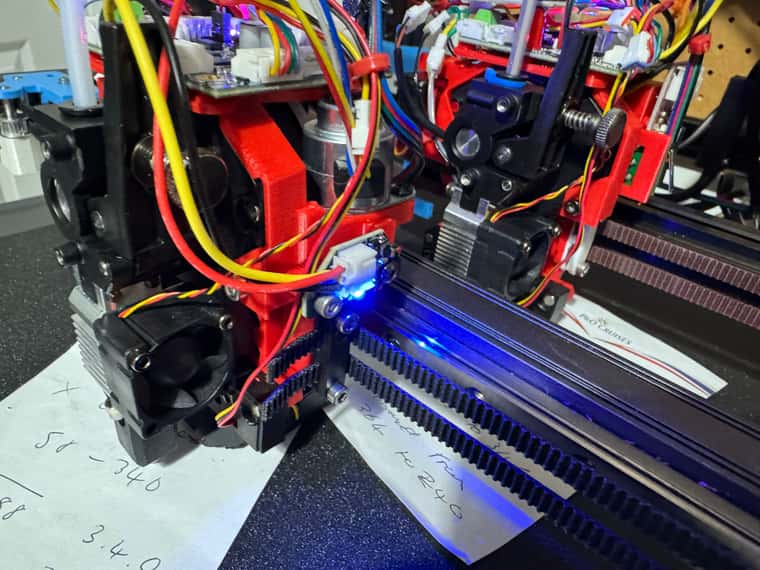
Wired up two types of z-hopper steppers - on the Mini5+ board
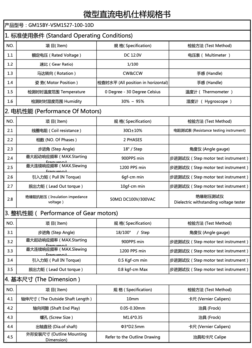
They both seem to move ok - but the Geared stepper looks very small and I don't have a mA rating for them - but they are only £5 from PiHut.
The linear motor seems to work quite well - but it is a bit noisy on idle - so need to investigate that.
Relevant settings below - I put them on B and C axis for now - need to adjust the steps per MM for the the smaller geared motor - as it needs about 50mm movement for the spindle to turn.
; Smart Drivers
M569 P0.0 S1 D2 ; driver 0.0 goes forwards (Z axis)
M569 P0.1 S1 D2 ; driver 0.1 goes forwards (Z axis)
M569 P0.2 S0 D2 ; driver 0.2 goes backwards (Z axis)
M569 P0.3 S1 D2 ; driver 0.3 goes forwards (X axis)
M569 P0.4 S0 D2 ; driver 0.4 goes backwards (Y axis)
M569 P0.5 S0 D2 ; driver 0.5 goes backwards (Z axis)
M569 P1.0 S0 D3 V2000 ; driver 1.0 goes backwards (U axis)
M569 P1.1 S0 D3 V2000 ; driver 1.1 goes backwards (V axis)
M569 P1.2 S1 D2 ; driver 1.2 goes forwards (A axis)
M569 P1.3 S1 D2 ; Z-hopper 1
M569 P1.4 S1 D2 ; Z-hopper 2
M569 P121.0 S0 D2 ; driver 121.0 goes backwards (extruder 0)
M569 P122.0 S0 D2 ; driver 122.0 goes backwards (extruder 1)

; Motor Idle Current Reduction
M906 I30 ; set motor current idle factor
M84 S30 ; set motor current idle timeout

; Axes
M584 X0.3 Y0.4 Z0.1:0.2:0.0:0.5 U1.0 V1.1 A1.2 B1.3 C1.4; set axis mapping
M350 X16 Y16 Z16 U16 V16 A16 B16 C16 I1 ; configure microstepping with interpolation
M906 X800 Y800 Z800 U800 V800 A800 B50 C50 ; set axis driver currents
M92 X80 Y80 Z533.33 U100 V100 A533 B629 C629 ; configure steps per mm
M208 X0:300 Y-5:295 Z0:300 U0:300 V0:300 A0:300 B0:3 C0:3 ; set minimum and maximum axis limits
M566 X12000 Y12000 Z3000 U6000 V6000 A3000 B1000 C1000 ; set maximum instantaneous speed changes (mm/min)
M203 X42000 Y42000 Z3000 U21000 V21000 A3000 B1000 C1000 ; set maximum speeds (mm/min)
M201 X500 Y500 Z20 U250 V250 A20 B20 C20 ; set accelerations (mm/s^2)
I carried on using the configuration tool for as long as I could - but it seems to keep losing the !'s on my end stops - so switched to just editing config.g.
One thing I have noticed that I really like about Duet without RPI as how quick it boots up / restarts vs how long the Klipper based board that came with the SV08 took.
Also looking forward to be able to start prints much quicker than my X1Cs - which take about 7 or 8 minutes calibration before they start anything.
Specs for smaller geared stepper (pictured on right) attached below
-
@dwuk said in Sovol SV08 Multiple Motion System Upgrade.:
Next step - multiple motion system...
Fantastic work Dave. I am really looking forward to the first dual independent print!
-
Linear stepper looks fairly neat and hardly adds anything to the width - but can't test it properly until another MGN9C linear carriage arrives in a few days.
With the current plastic carriage it needs a little bit of help to lift at 150ma - but lowers very nicely.
There is always to option to add spring assist too if it struggles once it has the proper linear rail setup arrives.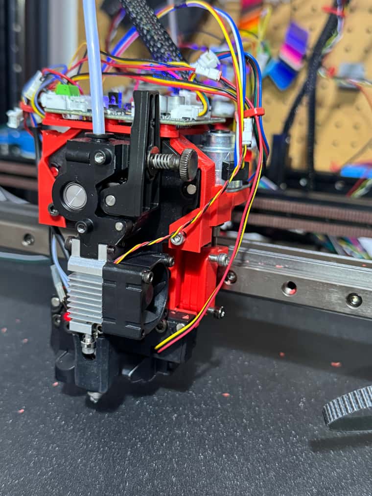
-
@dwuk Those motors are nice findings...but the small one might be too slow for anything? (15-20PPS @18degree/step divided by 100/1 gearbox) If my math is correct, it'll take 50 seconds for half a turn (outputshaft acting like hobby servo excenter)
You will also need a way to fix the tool in both directions. Otherwise the extruded filament will push it up. -
Just ordered two more 1LC tool boards and another mini5+ board.
That combination should allow for 6+7+5=18 axis drivers - z8, x4, y4 = 16 so should be enough for now - with the option to go up to 20 with another mini5 expansion.
Bad news is that my current mini5+ board is v1.02 - not sure what version E3D will send me for the 2nd board - their listing says 1.01 - so looks like some desoldering of terminator resistors on one of the boards is going to be required.
-
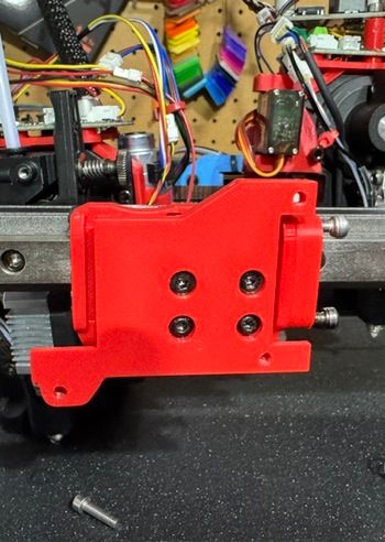
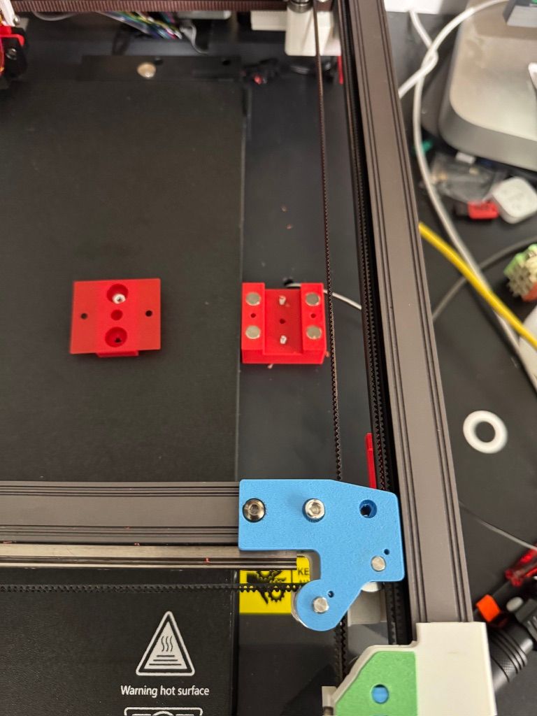
Added MGN9C carriage and Z lifter works quite well now.
See -
https://youtube.com/shorts/JexMhHyFkvI?si=BZMB12EFMrDNep2B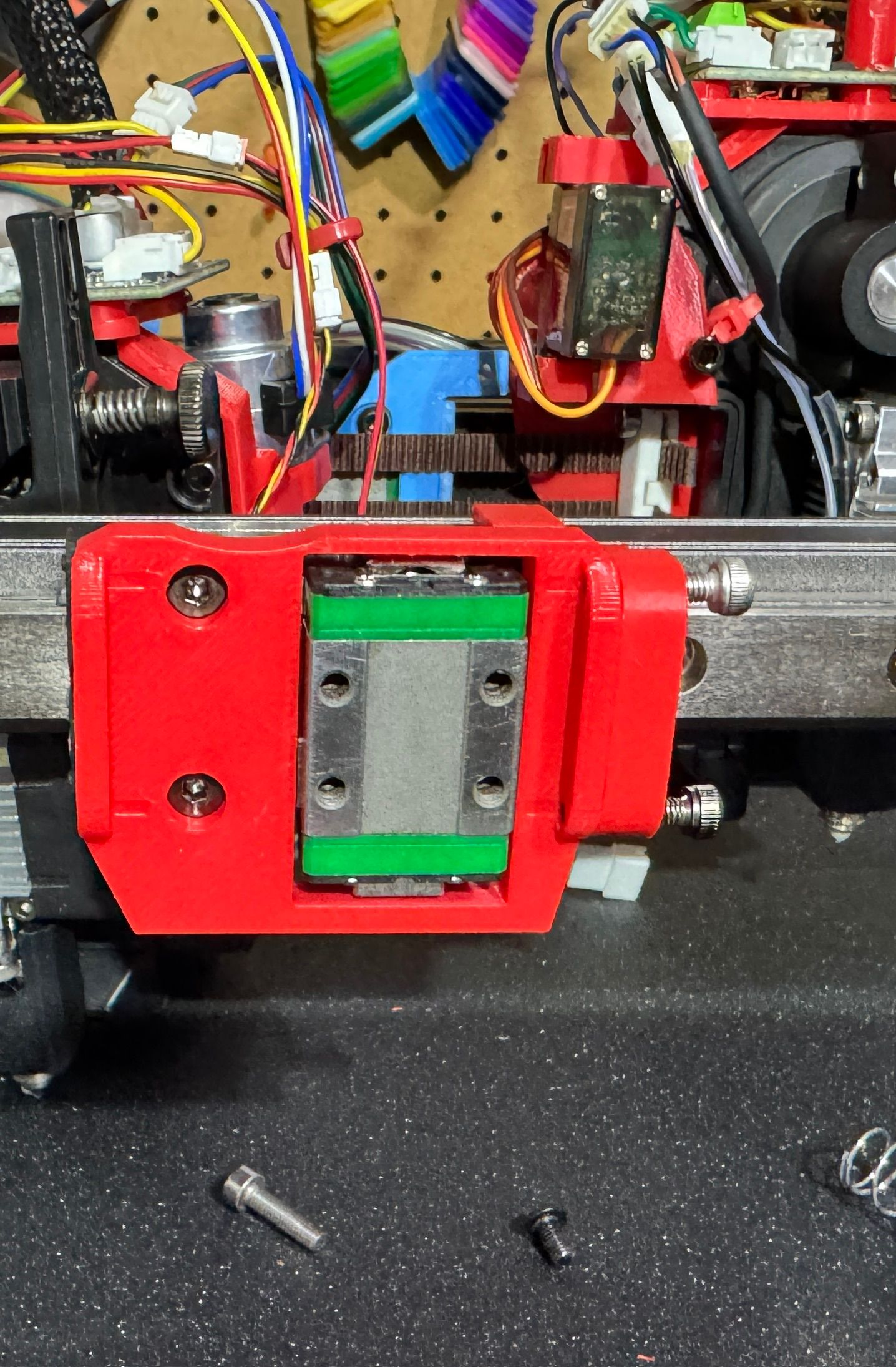
Next challenge after this is how to get a ball probe working with RepRap firmware to align the two heads - as per this Klipper add-on.
https://github.com/viesturz/NozzleAlign
I may have to do some maths in a macro to get this to work.
Am going to try one of the Ember Prototypes Camera based aligners too.
-
@dwuk i beleive @Sindarius has this concept working, hopefully he will be able to chime in.
-
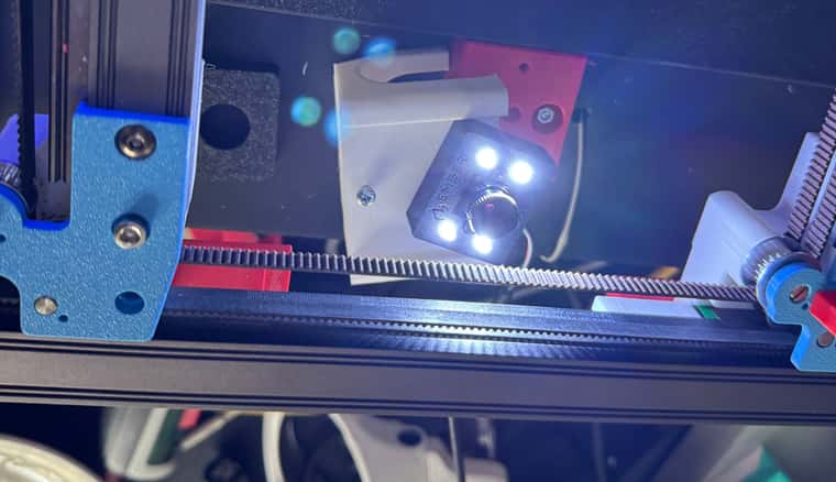
Added optical limit switch to front gantry linear Z hopper - and it is working pretty well.
The limit switch triggers at about -1.6 below the Z height of the other gantry, and the Z hopper can drop down by a further around 0.5mm.
So the 2.1mm difference also allows 'Voron Tap' type Z height detection to also work if the extruder is lowered down - although haven't yet implemented this in homeX.
I changed the M569 definition of the stepper from D2 to D3 and I think that has made it quieter - but it is staying a little hot on idle - so I need to add some switching off of IDLE's somewhere into the macros (M84 B) - however this does mean it loses it homing status. Maybe lowering the current percentage might work instead.
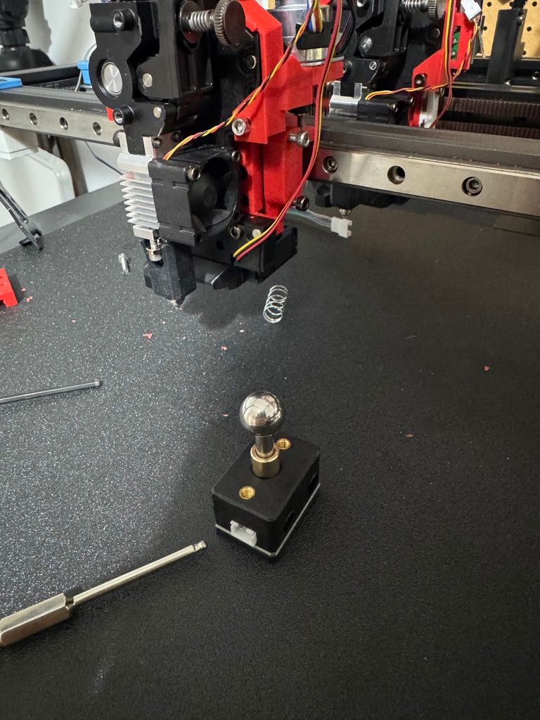
Next step tomorrow is to try some tests with the ball probe - I think I will just print something that I can place 4 magnets around it to hold it in a fixed place on the build plate for stability - and see what I can create in terms of macro code to accurately locate it on one gantry, then get the other gantry to do the same probing to get the two aligned.
Would be interesting to see what @Sindarius has developed for this too.
In terms of where the place the probe on the build plate.
It the short term I think I will just manually place it somewhere - bet ideally I would like to make the alignment fully automated. Am wondering whether it might be feasible to cut a small hole in the build plate and create a mechanism to lift the probe up from below when required.
Any prints over this area could potentially just bridge over the hole.
Haven't yet added any magnets to hold the front gantry extruder down - but I think something at 45 degrees like the voron tap can be added later once I get to some high speed printing tests.
-
Good progress made on Ball Probe
Demo of first attempt at Macro here - which I have initially done on the front Gantry
Video show G32 first, followed by Ball Probe alignment Macro
https://youtube.com/shorts/uPcV3BAuwyc?si=bT-t0YxPR4qDQWoo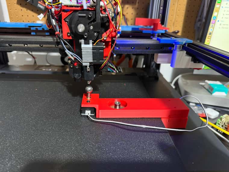
Held in place for now by Magnets - but I would like to automate the deployment and stowing of the Probe.
The 4 magnets at the edge are for basic positioning, with the larger one near the probe to hold it in place.
probe.g Macro - Currently just front Gantry
G90
G1 U150 V290 F20000
G1 Z50 F5000
G1 X235 Y179 F10000
M574 Z1 S2 K3; Set Z to Ball Probe

; Find basic Z position


G1 H4 Z-10 F300
echo "Z", {move.axes[2].userPosition}
G1 Z50 F300
G1 H4 Z-10 F300
echo "Z", {move.axes[2].userPosition}
G1 Z48 F300
G1 H4 Z-10 F100
echo "Z", {move.axes[2].userPosition}
var ZP = move.axes[2].userPosition

G1 Z50 F5000

M574 Z1 S2 K0; configure Z axis endstop

; Now find X middle

G91
G1 X-10 F5000
G90
G1 Z{var.ZP-0.2} F300


G91
M574 X1 S2 K3
G1 H4 X+10 F300

echo "X1", {move.axes[0].userPosition}

G1 X-5
G1 H4 X+10 F300

echo "X1", {move.axes[0].userPosition}

G1 X-5
G1 H4 X+10 F300

echo "X1", {move.axes[0].userPosition}
var X1 = move.axes[0].userPosition

G1 Z5 F300
G1 X10  F5000
G1 Z-5 F300

G1 H4 X-10 F300
echo "X2", {move.axes[0].userPosition}

G1 X5
G1 H4 X-10 F300
echo "X2", {move.axes[0].userPosition}

G1 X5
G1 H4 X-10 F300
echo "X2", {move.axes[0].userPosition}
var X2 = move.axes[0].userPosition

G1 Z5

G90
var XM = (var.X1+var.X2)/2
G1 X{var.XM}

M574 X1 S3 ; configure X axis endstop

; Now Y
G91

G1 Y-10 F5000
G1 Z-5 F300
M574 Y1 S2 K3

G1 H4 Y+10 F300
echo "Y1", {move.axes[1].userPosition}

G1 Y-5 F5000

G1 H4 Y+10 F300
echo "Y1", {move.axes[1].userPosition}

G1 Y-3 F5000

G1 H4 Y+10 F100
echo "Y1", {move.axes[1].userPosition}
var Y1 = move.axes[1].userPosition

G1 Z5 F300
G1 Y10 F5000
G1 Z-5 F300

G1 H4 Y-10 F300
echo "Y2", {move.axes[1].userPosition}

G1 Y5 F5000
G1 H4 Y-10 F300
echo "Y2", {move.axes[1].userPosition}

G1 Y2 F1000
G1 H4 Y-10 F100
echo "Y2", {move.axes[1].userPosition}
var Y2 = move.axes[1].userPosition

var YM = (var.Y1 + var.Y2) / 2


G1 Z5 F300

G90
G1 X{var.XM} Y{var.YM} F2000


G90

M574 Y1 S3 ; configure Y axis endstop
Results from test - to show level of consistency
19/02/2025, 22:32:59 Y2 182.625
19/02/2025, 22:32:57 Y2 182.625
19/02/2025, 22:32:56 Y2 182.625
19/02/2025, 22:32:53 Y1 174.275
19/02/2025, 22:32:51 Y1 174.300
19/02/2025, 22:32:49 Y1 174.288
19/02/2025, 22:32:44 X2 243.038
19/02/2025, 22:32:42 X2 243.038
19/02/2025, 22:32:40 X2 243.038
19/02/2025, 22:32:37 X1 234.812
19/02/2025, 22:32:35 X1 234.812
19/02/2025, 22:32:32 X1 234.812
19/02/2025, 22:32:28 Z 45.645
19/02/2025, 22:32:26 Z 45.647
19/02/2025, 22:32:23 M98 P"0:/macros/Probe.g"
Z 45.647 -
Impressive demo of SV08 toolchanger (phase 3 for me) here.
https://youtu.be/tg2vRfqMXYU?si=3NB5lVxPEerKP82u
One thought that that did occur is that it would work a lot faster if the tool rack had its own independent Z axis - so that the tools could be brought down much closer to the current build height, and then moved up as the print grows.
So yet another axis to add to my design - will probably do it with dual lead screws - as it doesn't need to be quick.
-
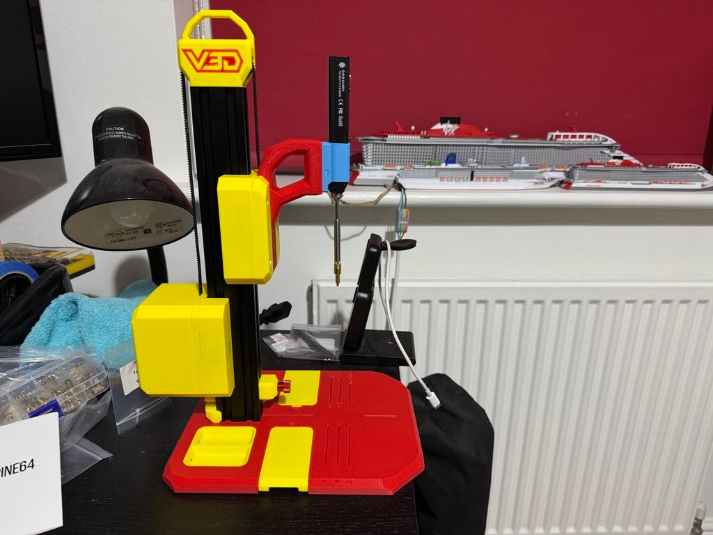
Got ball probes alignment macros (with loops and variables) working on the UV axis as well as the XY axis - both with the ball probe, plus also with an Ember Prototypes CXC - which is a camera pointing up at the nozzle.
Also created macros to search for the ball probe when it isn't quite where it is expected to be.
Alignment though is not that accurate yet.
The first problem that the camera has identified is backlash - which I am mainly getting on the UV axis, and more noticeably in the V direction. - its only about 0.1mm - but it does mean that if for example you move 10mm in the V direction and back you don't end up in the same spot. But if you move back another 10mm and then forward you get back pretty close to where you started.
Have tried removing the Phase2 IDEX carriage as I thought that might be impacting the movement - but that hasn't helped, plus have also tightened up the belts a fair bit - but am still getting the issue.
I guess it might be that my print head is not rigid enough - or it might be the motors.
Will try training the camera on other parts of the mechanism next to see if I can see where the backlash is coming from.
-
@dwuk Demo of backlash problem - comparison of the V vs Y belts.
-
@dwuk obviously removing the backlash is the best solution. however there is backlash compensation in the firmware:
https://docs.duet3d.com/en/User_manual/Reference/Gcodes#m425-configure-backlash-compensation -
@T3P3Tony Thanks -
By changing the Motor Pulleys - from 16 teeth to 20 teeth (as per Voron 2.4) and tightening up the belts on front idler mounts I have got the backlash down to between 0.05 to 0.1 - but it is still worse on the V motor the all of the others.
will try backlash compensation too - but after I have got it as small as possible by strengthening up a few of the parts and doing a bit of lubrication.
Plus also I am currently using quite a lot of bolts directly in to 3d prints (using the recent @ThomasSanladerer method) - so will have to add a few more nuts or threaded inserts to tension things up a bit more.
Have also got the @Vector3d Calibration Lantern - as I think I am going to have to get the XY & Z pretty accurate for the two heads to work reliably on the same print.
-
@dwuk Backlash won't be your primary problem when you use the "outer perimeter in one go" version of your gcode postprocessor.
I wouldn't spend too much time on it now and try to make a working proof of concept first.
You might have to redesign alot anyway, just put it on your ToDo list. -
@o_lampe good point.
I have got the backlash down to <0.1mm and it seems to be related somehow to the movement of the V axis.
Setting backlash compensation to 0.1mm on U and V with an S value of 1 seems to more or less mitigate it.
Also if it is related to the V axis then the move to dual Y + dual V would greatly simplify the belt structure for those Axis - so I moved last night back to looking at auto alignment with the ball probe, and will today start doing some printing of the Vector3d alignment lantern on both gantries (using duplicate mode).
Will also start moving the 3d printed parts away from mostly bolts into shaped plastic holes into threaded inserts (which I have always avoided in the past).
Built a Vector3d VLP2 over the last couple of days which was a fun project.
-
Got some good advice from 'Ken' on the Vector3d discord - so I think my immediate priorities now are:
- Consistent auto XYZ alignment using a ball probe - with XY checked using CXC.
- Keeping X&Y alignment across a large area of the build surface. - maybe I will just print a simple large squares for this and adjust steps/mm if necessary - and leave the Lantern until later as you suggest.
- Bed level Mesh adjustment - if necessary - (not sure how flat my bed is yet).
- 2 Colour IDEX testing
- Parallel printing of separate Models
- Parallel printing on a single model.
In terms of other steps already completed:
- PID tuning done for the print heads - but I did get a warning message on the heat bed some will have to sort that out at some point.
- E Steps done
- Z Offset done - although quite a lot more gcode post processing work needed on this - as my print head have independent extra Z axis adjustment capabilities for independent Z hopping and mesh adjustment.
Will then I think do:
7) Speed and acceleration tuning
8 ) Adding print heads 3 & 4 - and repeating most of the above. - my 2nd Mini5+ board ended up being V1.3 luckily - so no desoldering needed:)
9) Fan cooling - I had to take off one of the cooling fans from each head due to Duet tool board connection issues (plus print head size) - think I will try running extra cables for the 2nd cooling fans direct from the main boards.- Retraction
- Input shaping
- Pressure advance
- Advanced calibration using Vector3d Lantern.
- Z hopping and multi head mesh adjustment
- Tool changer - probably just two extra tools initially on the front gantry
- Filament management - which will probably need some sort of custom AMS/MMU to be developed - that can handle splitting spools into up to 4 separate strands for the 4 print head parallel prints and occasional colour swaps that can't be accommodated by the tool changer part of the printer.
-
Having a few problems with Multiple motion system - I think I am going to need some @dc42 help.
On 3.5.4 - It works ok with some basic commands as below:
With both gantries moving in parallel in different directions ok.M595 Q1 P5 M595 Q0 P5 M596 P1 G90 G1 U100 F500 G1 U200 F500 G1 V300 F500 G1 V250 F500 M596 P0 G1 X200 F2000 G1 X100 F2000 M598 G1 Y20 F1000 G1 Y50 F1000 G1 X200 F2000 G1 X100 F2000However Problems are:
- M598 does not seem to work - as the G1 Y20 F1000 just carries on - even though the U axis moves haven't completed.
- If I set the Queue size above 5 the motion in Queue 1 (M596 P1) - G1 moves goes haywire - just doing a G1 U1 for example moves the gantry to the back and beyond with a grating sound.
I noted that on the 3.6.0 beta4 notes that there is mention of some sort of M598 fix - so tried a firmware upgrade to that version.
Firstly this resulted in me somehow tanking my 6HC firmware completely so I had to erase and reset it back to 3.5.4, then I also messed up the Mini5+ firmware too somehow - so again had to erase and reset it.
Eventually got it working again, and managed to do the 3.6.0 Beta Change on all boards.
Problem then with 3.6.0 beta 4 - was:
-
My homeall.g sequence no longer worked - it seemed to just to X and Y then stop - so I had to individually home each axis.
Also The U & V axis homing didn't seem to move the same - I am using switches - but I wonder if there is some sort of hangover from when I tried to get it to work on sensorless (which I would still quite like to do) - as the ball probe alignment would probably now be good enough. -
I then kept getting messages about the U axis already being in use when I ran the test script that worked ok on 3.5.4 (apart from M598 and M595 issues).
So decided to revert back to 3.5.4 and ask for help.
Config.g
; Configuration file for RepRapFirmware on Duet 3 Main Board 6HC ; executed by the firmware on start-up ; ; generated by RepRapFirmware Configuration Tool v3.5.10 on Wed Jan 29 2025 10:20:21 GMT+0000 (Greenwich Mean Time) ; General G90 ; absolute coordinates M83 ; relative extruder moves M550 P"Duet 3" ; set hostname ; Network M552 P0.0.0.0 S1 ; configure Ethernet adapter M586 P0 S1 ; configure HTTP M586 P1 S1 ; configure FTP ; Wait a moment for the CAN expansion boards to become available G4 S2 ; Smart Drivers M569 P0.0 S1 D2 ; driver 0.0 goes forwards (Z axis) M569 P0.1 S1 D2 ; driver 0.1 goes forwards (Z axis) M569 P0.2 S0 D2 ; driver 0.2 goes backwards (Z axis) M569 P0.3 S1 D2 ; driver 0.3 goes forwards (X axis) M569 P0.4 S0 D2 ; driver 0.4 goes backwards (Y axis) M569 P0.5 S0 D2 ; driver 0.5 goes backwards (Z axis) M569 P1.0 S0 D3 V2000 ; driver 1.0 goes backwards (U axis) M569 P1.1 S0 D3 V2000 ; driver 1.1 goes backwards (V axis) M569 P1.2 S1 D2 ; driver 1.2 goes forwards (A axis) M569 P1.3 S1 D3 ; Z-hopper 1 M569 P1.4 S1 D3 ; Z-hopper 2 M569 P121.0 S0 D2 ; driver 121.0 goes backwards (extruder 0) M569 P122.0 S0 D2 ; driver 122.0 goes backwards (extruder 1) ; Motor Idle Current Reduction M906 I30 ; set motor current idle factor M84 S30 ; set motor current idle timeout ; Axes M584 X0.3 Y0.4 Z0.1:0.2:0.0:0.5 U1.0 V1.1 A1.2 B1.3 C1.4; set axis mapping M350 X16 Y16 Z16 U16 V16 A16 B16 C16 I1 ; configure microstepping with interpolation M906 X800 Y800 Z800 U800 V800 A800 B150 C50 ; set axis driver currents M92 X80 Y80 Z533.33 U80 V80 A533 B629 C629 ; configure steps per mm if exists(global.vMin) == false global vMin = 120 global vMax = 330 global yMin = -5 global yMax = 210 M208 X0:315 Y-5:210 Z0:300 U35:350 V120:330 A0:300 B0:3 C0:3 ; set minimum and maximum axis limits M566 X12000 Y12000 Z3000 U6000 V6000 A3000 B1000 C1000 ; set maximum instantaneous speed changes (mm/min) M203 X42000 Y42000 Z3000 U21000 V21000 A3000 B1000 C1000 ; set maximum speeds (mm/min) M201 X500 Y500 Z20 U250 V250 A20 B20 C20 ; set accelerations (mm/s^2) ; Extruders M584 E121.0:122.0 ; set extruder mapping M350 E16:16 I1 ; configure microstepping with interpolation M906 E800:800 ; set extruder driver currents M92 E492:492 ; configure steps per mm M566 E120:120 ; set maximum instantaneous speed changes (mm/min) M203 E3600:3600 ; set maximum speeds (mm/min) M201 E250:250 ; set accelerations (mm/s^2) ; Kinematics M669 K8 ; configure CoreXYUV kinematics ; Probes M558 K0 P8 C"121.io1.in" H5 F1200 T18000 ; configure unfiltered digital probe via slot #0 G31 P500 X-17 Y10 Z2.55 ; set Z probe trigger value, offset and trigger height M558 K1 P8 C"122.io1.in" H5 F1200 T18000 ; configure unfiltered digital probe via slot #1 G31 P500 X-17 Y10 Z2.55 ; set Z probe trigger value, offset and trigger height M558 K2 P8 C"!121.io2.in" H1 F300 T300 ; configure unfiltered digital probe via slot #2 M558 K3 P8 C"io3.in" H1 F300 F300; Ball Probe ; Endstops M574 X1 S3 ; configure X axis endstop M574 Y1 S3 ; configure Y axis endstop M574 Z1 S2 K0; configure Z axis endstop M574 U2 P"!122.io0.in" S1 ; configure U axis endstop M574 V2 P"!122.io2.in" S1 ; configure V axis endstop M574 A1 P"1.io0.in" S1 ; configure A axis endstop M574 B1 S2 K2 ; Sensors M308 S0 P"temp0" Y"thermistor" A"Heated Bed" T100000 B4725 C7.06e-8 ; configure sensor #0 M308 S1 P"121.temp0" Y"thermistor" A"Nozzle" T110000 B4487 C6.95777e-8 ; configure sensor #1 M308 S2 P"122.temp0" Y"thermistor" A"Nozzle2" T110000 B4487 C6.95777e-8 ; configure sensor #2 ; Heaters M950 H0 C"out0" T0 ; create heater #0 M143 H0 P0 T0 C0 S105 A0 ; configure heater monitor #0 for heater #0 M307 H0 R2.43 D5.5 E1.35 K0.56 B0 ; configure model of heater #0 M950 H1 C"121.out0" T1 ; create heater #1 M143 H1 P0 T1 C0 S305 A0 ; configure heater monitor #0 for heater #1 M307 H1 R2.43 D5.5 E1.35 K0.56 B0 ; configure model of heater #1 M950 H2 C"122.out0" T2 ; create heater #2 M143 H2 P0 T1 C0 S305 A0 ; configure heater monitor #0 for heater #2 M307 H2 R2.43 D5.5 E1.35 K0.56 B0 ; configure model of heater #2 ; Heated beds M140 P0 H0 ; configure heated bed #0 ; Fans M950 F0 C"121.out2+out2.tach" ; create fan #0 M106 P0 S0 L0 X1 B0.1 ; configure fan #0 M950 F1 C"121.out1+out1.tach" ; create fan #1 M106 P1 C"Hotend" S0 B0.1 H1 T45 ; configure fan #1 M950 F2 C"122.out2+out2.tach" ; create fan #2 M106 P2 C"E2Cool" S0 L0 X1 B0.1 ; configure fan #2 M950 F3 C"122.out1+out1.tach" ; create fan #3 M106 P3 C"Hotend2" S0 B0.1 H2 T45 ; configure fan #3 ; Tools M563 P0 D0 H1 F0 ; create tool #0 M568 P0 R0 S0 ; set initial tool #0 active and standby temperatures to 0C M563 P1 D1 H2 F2 ; create tool #1 M568 P1 R0 S0 ; set initial tool #1 active and standby temperatures to 0C ; Miscellaneous ; Custom settings M915 X Y U V R0 F0 M671 X410:-60:-60:410 Y420:-10:420:-10 S7 M307 H1 R7.427 K0.701:0.030 D1.50 E1.35 S1.00 B0 V24.5 M307 H2 R7.020 K0.857:0.148 D1.65 E1.35 S1.00 B0 V24.0 M307 H0 R0.527 K0.163:0.000 D5.70 E1.35 S1.00 B0 M557 X0:200 Y0:220 S20 M950 S1 C"122.io0.out" M280 P1 S60 ;M42 P1 S0 ; Allow movement without homing ;M564 S0 H0 ; Tools ;Tool T1 - 2nd Gantry as X and Y M563 P1 D1 H2 X3 Y4 F1 G10 P1 X0 Y0 U0 V0 S0 R0 ; T2 - duplicate mode M563 P2 D0:1 H1:2 X0:3 Y1:4 F0:1 G10 P2 X0 Y0 U0 V-150 S0 R0 M567 P2 E1:1 M568 P2 S1 ; Backlash compensation M425 U0.1 V0.1 S1 -
@dwuk It would be good to work out why homing was not working as expected in 3.6beta4. Where have been a lot of changes between 3.5.4 and 3.6 so the release notes may explain why. If not then please share your U and V homing files so we can have a look at those.
-
@T3P3Tony I think as you suggest I will go back to 3.6.0b4 and investigate the homing issue a bit more.
I guess I could also try doing the homing of the two axes in parallel too - to see if that helps.